This thread has been locked.

If you have a related question, please click the "Ask a related question" button in the top right corner. The newly created question will be automatically linked to this question.

DP83867IR: Unable to receive/transmit packets over DP83867IRPAP In U-Boot

Part Number: DP83867IR

Hello,

We have connected an ethernet phy DP83867IRPAP device to our custom silicon on our in-house developed board, and the bootstrap is set to configure the device in RGMII mode, Autoneg enabled. In RGMII mode 1G we could see the device responds properly, the link is set up, and with Autoneg enabled, we could see the phy configures itself into either 100Mpbs or 1Gbps based on the type of connected peer.

Unfortunately, we are unable to transmit/receive ICMP packets (ping) from our target to the host for 100/1000 speed.

-Delay control register is set to 0x77. i.e 2ns for both TX and RX.
-In the U-Boot environment (2020.07-rc3). When we trigger ping from target to Host PC we don't receive any reply.
We see the "host 192.168.x.x is not alive"
-We started tunning the Delay control register (RGMIIDCTL) with value 0x08 i.e TX delay set to 2.25 NS
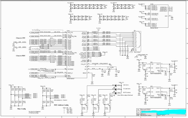
At the hardware level, we have verified that the clock and reset are fine.

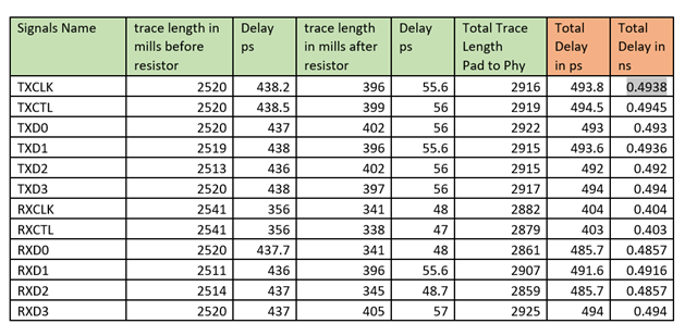
The trace lengths between the MAC and PHY interface on PCB are as follows:

We could see that if we ping from target with the delay control registers (RGMIIDCTL) set to 0x0 i.e both RGMII_RX_DELAY_CTRL/RGMII_TX_DELAY_CTRL set to 0.25 ns
the connected PC reports RX ERROR in ifconfig.

-TX_CLK: 2.5/25/125 MHz for 10/100/1000 speed gen.

-Reset: The phy is out of reset, and register/read/write looks to be working fine.

Software Aspect:

1. Bootstrap is confirmed at STRAP_STS1 and 2 registers:
We have:
PHY_ADDR: 00001
RGMII Disable is set to 0
ANEG is enabled
RGMII clock skew is enabled

2. The attached mac tx/rx packet count registers show that packets are transmitted from the target.

3. On host side, the tcpdump/wireshark tool is unable to receive any packets from the target.

4. The dt node has following entries set:
phy-mode = "rgmii-id";
phy-handle = <&phy0>;
phy-reset-gpios = <&portc 25 GPIO_ACTIVE_LOW>;
max-speed = <1000>;
status = "okay";
ti,rx-internal-delay = <7> ; -> //We have tried for the entire range from 0 to 0xf
ti,tx-internal-delay = <8> ; -> //We have tried for the entire range from 0 to 0xf
ti,fifo-depth = <DP83867_PHYCR_FIFO_DEPTH_4_B_NIB>;
enet-phy-lane-no-swap;
ti,dp83867-rxctrl-strap-quirk;

5. We have also checked tuning the rx/tx internal delays over the entire valid scale of 0x0 to 0xf, but it didn't prove to be helpful.

6. The phy / mac register dump doesn't show any error event's triggered.

Could you please help us here, and let us know what we might be missing.
Please let me know if we need to share any specific information in order to analyze this better and get the issue resolved.

Thanks & BR,
Sagar Kadam

  • Hi Sagar,

    What is the RGMII TX and RX delay set to on the MAC?

    Also, it will be helpful to isolate this problem to either the MAC or MDI side of the PHY. Can you perform an analog loopback test, as well a reverse loopback test described in section 8.4.4 of the datasheet? This can give us a clue where to investigate further. 

    Thanks,

    David

  • Hello David,

    Appreciate your prompt reply.
    Initially, it was set such that: TX DELAY=0.25ns and RX DELAY = 2.25ns, but since this doesn't work, we have further analyzed it by iterating a loop such that
    For each ping request, with RX DELAY set to 0.25 ns the tx delay increases from 0.25 ns to 4.00 ns, then step up RX DELAY to 0.5ns the tx delay increases from 0.25 ns to 4.00 ns and so on.
    So for the entire range of Delay, we were not successful in transmitting valid packets to the client.

    Yes, we are trying to figure out how loopback can be checked on the target in the U-Boot environment and will update you on the results.

    Thanks & BR,
    Sagar

  • Hi David,

    Also, the additional query is we understood that we need to follow a certain set of sequences for putting the Phy in respective loopback mode, we couldn't identify how the results would be inferred as pass/failed.
    Is there any requirement for PRBS Settings to be done?
    In U-Boot we follow:
    1. Configure the network interface using setenv ipaddr 192.168.10.10
    2. ping  192.168.10.10 (Same IP address)
    3. expectation is if Analog loopback is enabled, we should get acknowledgement "is alive" (Is this right?)
    Please let us know if we are doing something wrong here.

    Thanks & BR,
    Sagar

  • Hello David,

    Further update on our analysis and Loopback mode testing:


    1. We observed the ETH0_TXCLK for 10/100/1000 bps. What we observed was that the amplitude of the clock changes as follows:
              10 Mbps: 1.8 V
            100 Mbps: 2.0 to 2.1 V
                1 Gbps: 1.1 V
         Is this expected?
     

    2. At 10 Mbps we have a working network connection. Target is able to ping the host with RX / TX Delay set to 0.25 ns.
        The PCB trace delays for the relevant traces are attached initially in this thread.

    3. We enabled MII Loopback in this stage, the sequence followed for the same is:


    rd_dt = phy_read(phydev, MDIO_DEVAD_NONE, DP83867_CTRL);
    phy_write_mmd(phydev, DP83867_DEVADDR, DP83867_CTRL, rd_dt | 0x8000);

    rd_dt = phy_read(phydev, MDIO_DEVAD_NONE, DP83867_RGMIICTL);
    phy_write_mmd(phydev, DP83867_DEVADDR, DP83867_RGMIICTL, rd_dt | 0x00D3);

    phy_write_mmd(phydev, DP83867_DEVADDR, MII_DP83867_BISCR, 0x0040);

    rd_dt = phy_read(phydev, MDIO_DEVAD_NONE, MII_BMCR);
    phy_write_mmd(phydev, DP83867_DEVADDR, MII_BMCR, 0x4100);

    rd_dt = phy_read(phydev, MDIO_DEVAD_NONE, DP83867_CTRL);
    phy_write_mmd(phydev, DP83867_DEVADDR, DP83867_CTRL, rd_dt | 0x4000);

    4. We observed that after sending the ping request only the MAC's TX count register increases as per the number of packets sent.
         But the RX Packet counter of the mac doesn't receive any packets?
    5. In PHY we don't see any RX/TX packet counter, is there something that we are missing to infer?
    6. The behavior and observation are the same in the case of Digital Loopback as well.

    The timing requirement doc specifies the following sequence for setting the Digital Loopback.
    What are the implications of the bootstrap pins, or other PHY registers when we are testing loopback mode?
    Do the default register values or any other settings apart from below mentioned registers interfere with loopback mode operation causing it to fail?
    From the document, it is unclear as to how to confirm whether loopback is passed/failed, could you please elaborate on how to achieve this?

    It would be good if you could shed light on the above queries as these are blocker and high priority.

    Thanks & BR,
    Sagar

  • Hi Sagar,

    Clock amplitude is expected to equal VDDIO, 1.8V in your case, for all speeds. This may be worth investigating.  

    Ping requests are not the appropriate command to be testing in loopback mode. PRBS generator and checker should be used instead. Please conduct a reverse loopback test and use PRBS from the link partner side to push and check data, as well as the MII loopback test pushing PRBS data from the MAC side. As you noticed, these instructions are listed in section 2.8 of the troubleshooting guide. There are not any other register or strap values that would interfere with this test. 

    Can you also provide scope shots of the RGMII signals (RX_CLK and RX_D0 at the PHY, as well as TX_CLK and TX_D0 at the MAC). 

    Your schematic looks okay. Though, why are TX_D4-TX_D7 pins shorted to ground? They should be left floating if unused. 

    Thanks,

    David

  • Hello David,

    Apologies for the delayed reversal, we were also doing certain experiments on our end for loopback test.

    We enabled the MII loopback and were able to see that the TX and RX packet counters were increasing relatively w.r.t the number of frames transmitted with ping. There are certain registers into the MAC which we are observing for analysing this:

    MII Loopback

    100 Mbps

    1000 Mbps

    Comments

    Tx_Octet_Count_Good_Bad 0x714

    Y

    <TBD>

    Count increases relatively as per frames
    transmitted.

    Tx_Packet_Count_Good_Bad 0x718

    Y


    Tx_Packet_Count_Good 0x768

    Y


    RX_Packets_Count_Good_Bad 0x780

    Y


    Count increases relatively as per frames
    Received.

    Rx_Octet_Count_Good_Bad 0x784

    Y


    Rx_Octet_Count_Good 0x788

    N


    Since No good packets are received, this counter doesn't increase

    RX_Alignment_Error_Packets 0x798

    Y


    Erroneous condition is observed.
    We get RX Alignment Error packet indicator

    We would like to know :

    1) If the phy is configured into loopback mode then, what may be the reason we are seeing data loss.
    Suppose we transmit 4 frames via ping (each of 64 bytes) then a total of 256 bytes should be looped back by the phy to the mac, but what we observe is that the mac just receives 252 bytes, and due to this, it might be triggering an RX Alignment error. It's unclear what is it within the PHY that is trimming 4 bytes of data.

    2) As you suggested If we want to use PRBS generator and checker, will we have to use another board as link partner having the same phy or it is also possible on any client PC running Linux in it? If yes, could you please help with the steps to do so as it is a bit unclear on the setup required and steps to execute?

    3) If we are running Near-End Loopback, can we use the PRBS generator and checker on the same device to verify loopback? If yes how?

    4) What is the acceptable Skew between TX_CLOCK and TX_Data lines? We are currently observing following skews when measured at the receiver i.e the PHY side (R368 and R370)

    100 Mbps TX Data Lines skew w.r.t Clock RX Data Lines skew w.r.t Clock
    D0 320 ps N/A since no response
    D1 5.600 ns N/A since no response
    D2 5.400 ns N/A since no response
    D3 5.200 ns N/A since no response

    Since we have 10 Mbps functional we tried to analyze there as well:

    10 Mbps TX Data Lines skew w.r.t Clock RX Data Lines skew w.r.t Clock
    D0 880 ps 200 ps
    D1 5.70 ns 200 ps
    D2 5.40 ns 200 ps
    D3 5.20 ns 200 ps

    The skews in both 10 and 100 Mbps look to be similar, is this within the acceptable range?

    5) The TXD4 to TXD7 are grounded as per the recommendation within the datasheet. Please let us know if we have misinterpreted the below recommendation wrongly.

    Could you please help us with the above queries?
    I will recapture the RX and TX clock with the latest experiments and share it.

    Thanks & BR,
    Sagar

  • Hi Sagar,

    1) Looks like there is some corruption of packets happening on the MAC interface. Looking at your skew table in number 4) of your previous reply, this is likely the cause of your issues. Why is the D0 skew so much different than the other 3 data lines?  Your traces are length matched according to your first post, so where is this additional skew for D0 coming from? All 4 data lines should have very close amount of skew. 

    RGMII timing specifications are listed in section 7.9 of the datasheet. Data to Clock input Skew should be within 1 and 2.6ns, so you are not meeting that requirement. No matter the tuning you are doing, since D0 skew is much different than D1-D3, all 4 lines will never meet the spec. This explains why you were not able to find a viable tuning option. First you must fix the D0 skew to be equal to the others, then you can do the tuning experiments as you have done before. 

    2) Yes, for reverse loopback test you have to use a link partner capable of generating and checking MAC packets or PRBS. If you use another DP83867 for this, the PRBS generation/checking is described in section 8.4.5 of the datasheet. If this reverse loopback test is successful, it will confirm the issue is on the MAC interface. 

    3) No, must use packet generator/checker coming from the MAC for near-end loopback.

    4) Answered in 1)

    5) You are correct, termination to ground is fine.

    Seems like this issue is coming down to RGMII timing, so ensure the timing meets the specs listed in section 7.9 of the datasheet, and I am suspecting this will resolve your issue.

    Thanks,

    David

  • Thank you, David, for providing your inputs, we will check on the reason for variation in skews between D0 and D1-D3.

    Thanks & BR,
    Sagar

  • Also if the skew's are not right, we were wondering how come it is working for 10 Mbps data rate?

    Thanks & BR,
    Sagar

  • Hello David,

    #3) As you mentioned about using "packet generator/checker coming from the MAC for near-end loopback." in case of near-end loopback.

    We checked within the MAC IP documents, and don't see any PRBS generator or checker available for this purpose.
    In that case should we continue with ping as a test utility or you have some other suggestions for this purpose.

    Thanks & BR,
    Sagar

  • Hi Sagar, 

    The timing requirements are less stringent on 10 and 100Mbps, since the clock cycles are much slower, so your setup may not meet the setup/hold requirements for 1000Mbps, but still be able to operating in 10 or 100. 

    From my limited understanding, it seems like the registers Rx_Octet_Count_Good_Bad 0x784, Rx_Octet_Count_Good 0x788, and RX_Alignment_Error_Packets 0x798 are doing the MAC packet checking, so you can continue to use that. Is my understanding correct?

    Thanks,

    David

  • Hello David,

    Just to keep you posted. We are working towards matching the skews as we discussed earlier. We are tuning the drive strengths of the MAC interface signals. 

    Additionally, based on our observations and the skews, we thought of setting the RGMII_TX_CLK_DELAY/RGMII_RX_CLK_DELAY to 0 i.e set TX/RX to be aligned with the clock, for which we wrote 0x00 over there, and to our surprise, we see that 100 Mbps works but 1Gbps fails in U-Boot.

    But what we couldn't understand is setting the RGMIICTL to 0x0 disables RGMII Enable Bit and the phy starts to operate in GMII mode as per following context into the datasheet, whereas on board the interface is RGMII. 

    8.4.1 MAC Interfaces
    The DP83867 supports connection to an Ethernet MAC via the following interfaces: RGMII, GMII, and MII.
    The RGMII Disable strap (RX_D6) determines the default state of the MAC interface. The RGMII Disable strap
    corresponds to the RGMII Enable (bit 7) in the RGMIICTL register (address 0x0032). When RGMII mode is
    disabled, the DP83867 operates in GMII mode.

    Could you please shed some light here? How does it work in U-Boot even if phy is wrongly configured?
    it might be because of an invalid / wrong configuration 1G might not be working.

    Thanks & BR,
    Sagar Kadam

  • Hi Sagar,

    Why do you want to operate the device in GMII? Your schematic is not configured for GMII. Please keep bit[7] of the RGMIICTL register as 1 to continue using RGMII and tuning as you have been doing to meet the specs listed in section 7.9 of the datasheet.

    Thanks,

    David