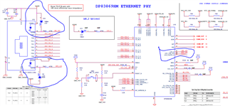
Below are the sch. Kindly check & give me your suggestion

This thread has been locked.
If you have a related question, please click the "Ask a related question" button in the top right corner. The newly created question will be automatically linked to this question.
Hello,
What is the functionality you are trying to accomplish with this? Can you please check your settings for LED configuration on Reg 0x18, 0x19? In addition, you can also take status of the PHY with registers 0x1 (link), 0x11 (speed).
Sincerely,
Gerome
Hello,
If the PHY is under default conditions (ie no programming made), then the LED's will act as the following:
LED0: Link
LED1: 1G Link
LED2: Activity
If this is the following, then 2 situations come to mind, assuming the PHY is set up correctly (power rails good, clk_out on, activity on the MDI line, etc):
1) You are not getting link. This would explain why LEDs are not turning on, but it is harder to debug as you do not have register access available. What is the link partner you are connecting to in this case? What cabling is being used (type and length)?
2) LED driver is active high. In datasheet section 9.5.2, LED configuration states that "If a given strap input is resistively pulled low then the corresponding output is configured as an active high driver." If you are getting link, then the LED pin would be driven high, while would cause the LED to turn off as there isn't sufficient voltage difference to satisfy LED turn-on voltage. This would require a change in layout to fix, or register access to make the pin an active low.
Sincerely,
Gerome
Hi Rajesh,
TI offers SMI tool for MSP430 which is connected to our PHY called USB2MDIO. Otherwise, any microcontroller that supports SMI communication can help, but you would need to figure out how to program that procedure.
Sincerely,
Gerome
Thanks for replying!!!
We have configured the PHY in copper to SGMII mode which have below boot strap configurations.
JTAG TDO(PIN 22): OPEN
RX-D2(PIN 35): PULLED TO VDDIO WITH 2.49K RES
RX-D3 (PIN 36): PULLED TO VDDIO WITH 2.49K RES
Strap setting for functional modes:
1. LED0: Pulled to ground with 2.49K resistor
2. LED1: Pulled to ground with 2.49K resistor
3. LED2: Pulled to ground with 2.49K resistor
We have powered up and checked the voltage across the LED strap resistor which is 0V.
We could not able to establish the link at 100BASE-TX and SGMII.
Please verify the above straps, whether we have configured for Copper to SGMII or not.
Also, Help us to bringup the PHY.
Thanks.
Hello Rajesh,
I will be out of office for the rest of the week. I have this discussion queued up to bring up with team upon my return. Please expect a response by early next week. Thank you for your patience.
Sincerely,
Gerome
Hi Rajesh,
Your strapping looks fine. Those are the intended configurations. I would advise checking those pins while holding the PHY in reset state to ensure that nothing else is trapping the PHY that would have it deviate from these settings on these pins.
Can you also measure CLKOUT pin to ensure signal is within specifications as required in datasheet?
For further debug, it will be difficult to go further without microcontroller to look at register configuration to see if link is up from register standpoint.
Sincerely,
Gerome