This thread has been locked.

If you have a related question, please click the "Ask a related question" button in the top right corner. The newly created question will be automatically linked to this question.

DP83TG720R Sleep mode

Other Parts Discussed in Thread: DP83TG720R-Q1

I am working with the B0.1 sample for ADC500 and not the eval board.    

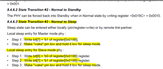
I had few observations regarding the additional steps required to put the DP83TG720R (1000 base T1) phy to sleep mode.

I see from the datasheet 

Here we have two observation we are currently using the linux phytool commands to make to communicate with phy2

phytool write eth0/5/0xD 0x001F
phytool write eth0/5/0xE 0x018B
phytool write eth0/5/0xD 0x401F
phytool write eth0/5/0xE 0x00C0 or phytool write eth0/5/0xE 0x0080

We are using the the indirect writing of the address as mentioned in the datasheet

Observation 1:

When we dont have the media convertor connected on the respective port of 1000 base T1 and we issue the above command either from the linux console via the UART or via the ssh 

We can see the inhibit pin going low which is the indication that it transit into the proper sleep.

Observation 2:

When we have the media convertor connected to the phy2 and try to issue the commands it doesnt go into sleep and i can see on the oscilloscope the phy2 inhibit pin high

Observation 3:

Suppose my media convertor is connected to the respective port of phy2 and then i issue the commands and then remove the phy2 physical connection then see on the oscilloscope i see that the inhibit pin goes low

I also kept the wakeup pin low i could see that the wakeup pin was low on the oscilloscope

What additional steps do  i need to take for 1000base T1 when media convertor is connected to make it into sleep or are we missing something ?

Now with the similar steps just register number change for 100 base T1 when the media convertor is connected we trigger enable sleep bit on the 0x183 register and it goes into sleep even when the media convertor is connected so wanted to know how is the 1000 base T1 acting different from 100 base T1 and the additional steps what we need to use.

  • Hello,

    Can you please provide block diagram of the system you are using? I am not able to fully follow.

    Sincerely,

    Gerome

  • Hello Gerome,

                           This is the high level diagram of the system we are using 

    Here the B1 board is the ECU and there we have ethernet ports

    From the canoe box which is V55620 these wire cables has two channels Channel A and Channel B and each channel has two wires coming out

    Then we have  a connector connected to the ECU and there 4 ports are coming out

    There in each of the port refers to a certain phy

    We connect wires from the ethernet cable coming from Canoe box and connect it to the ethernet ports there are basically db9 sub the ports from the ethernet having two wires white and light green which are being connected.

  • Hello,

    So just for my own understanding, DP83TG720 is on B1 board, and the link partner of the PHY is the VN5610A, correct?

    Sincerely,

    Gerome

  • Hello George,

                          You are right the link partner to the phy is one of the channels on VN5620 actually that block diagram has wrong name its VN5620 in my case but in general the CANOE box supporting ethernet is the link partner and the B1 board has the 1000 base T1 phy (DP83TG720R).

    Thanks and Regards,

    Nishesh

  • Hello,

    Please see the following for directions on sleep entry and exiting sequence for DP83TG720:

    Sleep Entry Sequence

    Initial condition: DP83TG720 linked up to link partner

    Step 1 : Program PHY (local and remote) to “allow sleep entry”.

    Step 2 : Make “Wake” pin low for both local and remote PHY

    Step 3 : “Initiate sleep request” from the required 720 PHY device.

    Step 4 : INH will go low on both sides after step 3. Use INH to disconnect the supply of both the PHYs.

    Script to allow sleep entry

    000D 001F

    000E 018B

    000D 401F

    000E 0180

    Script to initiate sleep request

    000D 001F

    000E 055F

    000D 401F

    000E 4000

    000D 001F

    000E 0560

    000D 401F

    000E 0000

    000D 001F

    000E 042F

    000D 401F

    000E 0007

    000D 001F

    000E 041E

    000D 401F

    000E 0100

    Sleep Exit Sequence

    Initial Condition = 720 PHYs are in sleep with their power cut-off

    If sleep exit is to be initiated by master device :

    Step 1 : Make “Wake” pin high on master device.

    Step 2 : INH will go high for master device. Use INH to enable the master PHY’s supply.

    Step 3 : INH will go high for slave device. Use INH to enable the slave PHY’s supply.

    Step 4 : Both master and slave are awake now.

    If sleep exit is to be initiated by slave device : 

    Step 1 : Make “Wake” pin high on slave device.

    Step 2 : INH will go high for slave device. Use INH to enable the slave PHY’s supply.

    Step 3 : Configure PHY to master mode. Stay in master mode for ~2ms.

    Step 4 : INH will go high for master device. Use INH to enable the master PHY’s supply.

    Step 5 : Revert back to original configuration of slave mode.

    Sincerely,

    Gerome

  • Hello Gerome,

                            Thank you for your reply and the details !!.

    As i can understand from the first part 

    allow sleep entry

    000D 001F

    000E 018B

    000D 401F

    000E 0180

    You are setting the address 18b to 180 meaning that bit 7 and 8 is set to 1

    Next is the part i am little confused or i am looking into a wrong manual i am not sure 

    Script to initiate sleep request

    000D 001F

    000E 055F

    000D 401F

    000E 4000

    Please correct me if i am wrong here we are trying to set the address 55f with a value 0x4000 assuming the above commands of 18b i mean the fromat of the commands but here in the user manual if i can see

    I cannot see the register 55f in the register maps can you please explain what this sequence of bytes are doing for the initiate sleep request please to have a good understanding 

    000D 001F

    000E 0560

    000D 401F

    000E 0000

    000D 001F

    000E 042F

    000D 401F

    000E 0007

    000D 001F

    000E 041E

    000D 401F

    000E 0100

    In further sequences also i couldnt understand what is these registers doing like 560, 42f,41e or i am assuming things wrongly here please help me to understand the sequence what bits are getting set here as i couldnt find these registers in the manual that i have or if you are reffering to some other manual can you please share the link for the same

  • Hello,

    Unfortunately, these registers are proprietary information and thus cannot be shared.

    Sincerely,

    Gerome

  • Hello Gerome,

                           Thank you for the information !!

    Is there no way we can get this information or is it only not available via this interface forum, or if you can help with the proper commuincation channel if there are any to get this information that would be helpful for us. I am working on jacinto 7 

    Thanks and Regards,

    Nishesh

  • Hello,

    We are unable to provide this information as it is proprietary information.

    Please note that any subsequent responses this week will be delayed as I will be out of office. I will reply back next week if there are any more followups.

    Sincerely,

    Gerome

  • Hello Gerome,

                           Thank you for your detailed explanation we are testing this part and will let you know the feedback meanwhile i had another topic but its related to the ethernet phy itself 100base t1(DP83TC812R)

    I am using the below commands for initiating the sleep mode can you help me with additional register setting i need to perform on top of the below register setting for the 100base t1 phy just incase some properietary register which may be present which we are not aware of and the the system setup is the same as above

    (DP83TC812) Register 0x183(set to sleep mode)
    phytool write eth0/10/0xD 0x001F
    phytool write eth0/10/0xE 0x0183
    phytool write eth0/10/0xD 0x401F
    phytool write eth0/10/0xE 0x4100

    Thanks and Regards,

    Nishesh

  • Hello,

    Please let me get back to you on this by end of week.

    Sincerely,

    Gerome

  • Hello,

    Thank you for your patience. There will be an application note regarding this topic coming out by July 11.

    In the meanwhile, to initiate sleep mode on DP83TC812, please program Reg 0x18C = 0x2.

    Sincerely,

    Gerome

  • Hello Gerome,

                            Thank you for your reply !!

    I tried the below settings without the link partner connected or the port connected from the ethernet channel to the ports as shown in the block diagram aboe

    phytool write eth0/10/0xD 0x001F
    phytool write eth0/10/0xE 0x0183
    phytool write eth0/10/0xD 0x401F
    phytool write eth0/10/0xE 0x4100 

    phytool write eth0/10/0xD 0x001F
    phytool write eth0/10/0xE 0x018C
    phytool write eth0/10/0xD 0x401F
    phytool write eth0/10/0xE 0x0002

    The inhibit line for the 100base t1 (DP83TC812) goes low and its fine

    Now when we have the link partner connected with the same commands 

    the inhibit line goes low and then immediately in a second it comes up again 

    I also tried only sending 

    phytool write eth0/10/0xD 0x001F
    phytool write eth0/10/0xE 0x018C
    phytool write eth0/10/0xD 0x401F
    phytool write eth0/10/0xE 0x0002

    but still the same behaviour

    So i am woundering when the link partner or the port is still connected to the respective phy where the command is sent is there any additional commands we need to send as you gave for the phy2.

    Thanks and Regards,

    Nishesh

  • Hello Gerome,

                           I also tried the below sequence 

    phytool write eth0/10/0xD 0x001F
    phytool write eth0/10/0xE 0x0444
    phytool write eth0/10/0xD 0x401F
    phytool write eth0/10/0xE 0x000c

    This i was taking a reference from the ticket 

    DP83TC812S-Q1: Local Sleep of DP83TC812S - Interface forum - Interface - TI E2E support forums

    Here also when i see the 

    BMSR Register (Address = 1h) [Reset = 0061h]

    The link status is up for the respective port and then i send the above command to set the inhibit pin to low

    When i see this , the inhibit pin goes low after i set the register 0x4444 to a value 0x0c and then in some time may be within a second it comes up again.

    Another trail

    phytool write eth0/10/0xD 0x001F
    phytool write eth0/10/0xE 0x0183
    phytool write eth0/10/0xD 0x401F
    phytool write eth0/10/0xE 0x4100

    Same observation in this case also the inhibit line goes low and comes up again.

    Now if i only send 

    phytool write eth0/10/0xD 0x001F
    phytool write eth0/10/0xE 0x018C
    phytool write eth0/10/0xD 0x401F
    phytool write eth0/10/0xE 0x0002

    Then the inhibit pin is high all the time only the thing is it waits for ack i feel from the link partner and it waits for sometime because i can see on the linux console during that time i cannot send any commands then after waiting for sometime it starts allowing to send the commands but the inhibit ping never goes low.

    I wanted to understand when we have the link partner as the Vector Canoe box (VN5620) is there any command expected from the CANOE box to the ECU which puts the ECU into sleep or what is the exact flow when we use this 0x18c register to a value 0x02 to initiate the sleep

  • Hello,

    Thank you for your query. The US offices are closed for July 4th. As such, I will relay this information to the team and look to get feedback around the middle of the week.

    Sincerely,
    Gerome

  • Hello Gerome,

                           Just to add another info i the phy is acting as a master 

    MMD1_PMA_CTRL_2 Register (Address = 1834h) -- i checked this register and the bit 14 was set i read it via the MMD1 access also 

    I tried to make it slave and i was successful to make it slave also and tried the above sequence but didnt get any luck 

    Thanks and Regards,

    Nishesh

  • Hi Nishesh,

    We are working to consolidate all of this information into the app note as previously discussed. Please read that once it becomes public and if there are any followup questions after reading that document, we can help answer on a new thread.

    Sincerely,

    Gerome

  • Hello Gerome,

                          Just to confirm that the application notes will have the sleep mode procedure for both 

    DP83TG720R-Q1 1000BASE-T1 and also DP83TC812x-Q1 100BASE-T1 and it will also include the register setting when the link partner is connected like the vector canoe box as the link partner .

    We are looking for both 1000base t1 phy and also the 100base t1 phy as mentioned above.

    May on 11th of july as you stated in the above ticket the application notes will be published can you please comment on this ticket with the link after it is published so i would be looking into the correct link

    Thanks and Regards,

    Nishesh

  • Hi Nishesh,

    I will look to link the app note once it goes online. I believe it will only address TC-10 which is available in DP83TC812, and not the sleep setting in DP83TG720.

    Sincerely,

    Gerome

  • Hi Nishesh,

    As an update, please expect the app note next week. Apologies for the delay.

    Sincerely,

    Gerome

  • Hello Gerome,

                           Thanks for the update !!

    Thanks and Regards,

    Nishesh

  • Thank you for your reply.

    Sincerely,

    Gerome