This thread has been locked.

If you have a related question, please click the "Ask a related question" button in the top right corner. The newly created question will be automatically linked to this question.

TCA9548A: TCA9548A no channel switching with I2C frequency <100KHz

Part Number: TCA9548A
Other Parts Discussed in Thread: LDC1614, LDC1614EVM

Hello there,

I found a really strange problem with my TCA9548A setup:

- I can read write / read back the control register as expected, have tested this with clk range 10Khz - 400Khz.

- Here the funny part: Channel switching commands will select a requested channel only if clock frequency is 100Khz or above,
  I have tested this with 10 Khz , 90Khz, 100Khz and 400Khz.

Example (based on clk 90Khz):

1.) Writing a value of 1 to control register.

2.) Reading back the control register return vale of 1, as expected.

3.) No communication possible with channel 1.

Example (based on clk 100Khz):

1.) Writing a value of 1 to control register.

2.) Reading back the control register return vale of 1, as expected.

3.) Communication working with channel 1.

I have double checked with scope that following points are OK:

- Selecting baud rate in the I2C API

- Bypassing the TCA9548A completely, MCU directly connected to I2C slaves. No problems found regardless clk frequency.


Any ideas greatly appreciated.

Regards

Jo

  • Additional test I have done:

    1.) select I2C master baud rate 100 Khz.

    2.) select  TCA98548A channel 1

    3.) change I2C master baud rate to 10Khz.

    4.) Establish cannel 1 communication with a slave device.

    That was all OK. Regarding reported problem, I have tested against chips from different suppliers- no difference.

    Regards,
    Jo

  • Hi Jo,

    Can you include some scope shots of the your write at 90 kHz? Just to confirm does the channel actually get enabled, are you able to see I2C communication on the other side or does it just stay high?

    Can you include a schematic of your setup?

    Best,

    Chris

  • Hello Chris,

    Thank you for your feedback.

    I can provide scope photos, but with 90Khz testcase only from the primary side (bus segment between MCU and TCA9548A),
    because at channel side no signals available- probing SDA and SCL shows nothing.

    And on the primary side, it works perfect to me- I can alter the control register byte regardless baud rate setting.

    Reading the datasheet, I was under the impression that the control register does directly reflect the physical state of the multiplexer
    channel status. But it looks all channel are disabled, as if the device would come out after power on, despite control register value
    is suggesting otherwise.

    Regarding schematic, I can not provide detailed original documents- please indicate if simplified (block-diagram style) schematic
    would help your support team at current stage.

    Today I have created a new test case, which was hardware-wise a bit more isolated from the original setup. The test result was exactly
    the same, reproducing the problem.

    - Connecting MCU I2C master to a Adafruit TCA9548A breakout board, same MCU board but without assembled TCA9548A part.
    - SCL0 and SDA0 lines (Channel 0) connected to one channel of our sensor target board. There are 7 channels, for this test case
      I have used only 1 channel. Each channel talks to 2 Ti LDC1614 devices, on their addresses 0x2A and 0x2B.
    - pull ups primary side (MCU board) 4k7 and at channel side (sensor board) 2k2.
    - All logic VDD 3.3VDC.

    The whole sensor board with all 7 channel connected works perfect, when issuing TCA9548A control register writes with I2C clock
    100Khz instead of 90Khz.

    The intention is to run the production units with 100Khz, so test cases with reduced I2C speed are not a door stopper right now.
    Nonetheless, I fear that some underlying problems are luring around, perhaps showing up never or later- so I am not very
    convinced to let it at that stage for production purposes.

    Regards,
    Jo

  • Hi Chris,

    Tomorrow back at work, I can arrange a new test case, hardware-wise even more isolated from the original setup:

    Letting MCU master talk to a Ti LDC1614 EVM board, with TCA9548A in between. I have such EVM board in office around,
    known to be in working condition. I would power then the EVM from the MCU target board by 3.3VDC.

    Such test should clearly show, whether or not the sensor target board is part of the problem.

    Regards,
    Jo

  • Hi Chris,

    The device datasheet says on first page that supported I2C speed is 0..400Khz.

    Further down, only the 2 standard modes are mentioned (100Khz and 400Khz).

    Can you kindly confirm, that channel selection is working reliable with non-standard I2C clock speed?

    Regards,
    Jo

  • Hi Chris,

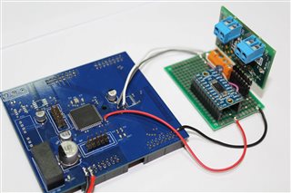
    I am not a fan of breadboards, so I have soldered a small adapter proto board hosting a Ti LDC1614 EVM board and an Adafruit
    TCA9548A board and connected to target MCU board. This is the board to the left on the photo, normally plugged in into the
    much larger sensor board (not shown):

    So with this setup, the sensor board with 13 LDC1614 devices is taken out of the equation, farther reducing
    hardware dependencies. All 4 pull up resistors 2k2. 

    Test result: Same issue. Communication with LDC1614 starts working at about 91Khz clock speed. And below that, when
    I probe with a scope secondary SCL and SDA lines, all what I see are very clean 3.3VDC levels.

    Do you still want me to provide SLC and SDA waveforms on 90Khz test-mode at primary side?

    My personal opinion is that the TDA9548A chip (at least the model on the Adafruit board) is simple designed for min. 100Khz
    operation in order to work correctly. Please let me know if this is not true.

    I appreciate your support, thank you.

    Regards,
    Jo

  • Hi Jo,

    I will read through all this information and get back to you tomorrow.

    Best,

    Chris

  • Hi Jo,

    I am going to test this in the lab I was able to find the right part. In the meantime can you send over a scope shot of the failing I2C communication. This device does not have a minimum I2C speed. The device works based off of an internal state machine and it will only increment the state machine when it sees the next clock pulse. So you can use whatever speed you want as long as your clock pulse lines up correctly.

    Best,

    Chris

  • Hello Chris,

    Great support, trying to replicate my test result.

    My problem is, as it stands for now, I am not seeing that the I2C communication is failing at any point- otherwise how comes that I can
    read back previously written control register at any clock speed? That means there must be an ACK (or NACK) coming from the I2C device.

    Regards,

    Jo

  • Hi Jo,

    When you say

    Test result: Same issue. Communication with LDC1614 starts working at about 91Khz clock speed. And below that, when
    I probe with a scope secondary SCL and SDA lines, all what I see are very clean 3.3VDC levels.

    This means that under 91 kHz your controller device (formerly known as master) is not able to send I2C data correct? Or is the data still able to send but the TCA9548A is not able to correctly decode the signal in order to change the internal control register.

    Best,

    Chris

  • Hi Chris,

    This is exactly what I don't understand- the MCU board (I2C master) is able to communicate with the TCA9548A module by addressing
    it with 0x70h and updating successfully the control register. At any clock speed at any time- tested between 10Khz and 400Khz, no issues.

    Only the multiplexer engine is picky with the clock, below 91Khz it is simply not switching anything. (As if the device is still in reset state,
    meaning all channels appear disconnected from the primary side).

    Regards,
    Jo

  • To be more precise, I meant with device channel 0- that is the channel connection to the LDC1614EVM as in my last test setup.
    I have not tested the remaining  channels. But after writing "1" to control register (and successful readback), I must assume that
    channel 0 is supposed to be the selected one- no other logical choice here, so I have omitted to test all channels with last test setup.

    On the real thing (the sensor board populated with 13 LDC1614 devices) 7 channels are working perfect, provided clock speed >= 91Khz.

    Regards,
    Jo

  • Hi Chris,

    Maybe worth mentioning one more technical detail I have not mentioned earlier:

    The adafruit module has RESET pin pulled up to VCC,  in my last test setup I have made no attempt
    to pull it low by microcontroller for a brief period of time for clean reset purposes.

    However, I did that with the production MCU controller board, there RESET pin of TCA9548A is pulled
    up with 10k resistor and also connected to a MCU pin for reset purposes.

    I can tell, there was no difference in reported test cases, whether or not resetting TCA9548A after power-on again.

    In general, there was no randomness with my test results- with 100Khz clock, all test setups (production as well as
    simplified setup) were running several hours without a single glitch or hang-up, I have tried this several times
    and all was stable. (The production sensor board is being switch through seven mux channels all the time as fast
    as possible with respect to 100Khz clock- no issues observed).

    And with 90Khz clock, mux switching the channels did not work at all- consistently repeatable.

    Regards,
    Jo

  • Hi Jo,

    I am having the chip soldered onto a breakout board and I will be able to test it tomorrow in the lab. If you can't provide any scope shots can you at least tell me what codes you are sending to the chip so I can replicate your test set up.

    Best,

    Chris

  • Hi Jo,

    I was able to test the chip today in the lab and I was able to get it to work all the way down to 10 kHz. I think at this point I am going to need to see some scope shots for me to be able to help you.

    Can you send a scope shot of your write at 90 kHz? Then if you have a 4 channel scope can you send a scope shot of a random I2C write, On two probes probe the SDA and SCL channel. Then on the other two probes probe the SD0 and SC0 channel. I want to see what happens to your driver as you slow down the speed.

    Best,

    Chris

  • Hello Chris,

    Thank you very much for testing, sorry for delayed reply. I will proceed with your requested tests asap with second assembled PCB when ready,
    another one is already in product prototype testing, so it will take a while- I will let you know.

    Regards,
    Jo

  • Hello Chris,

    In preparation for scope probing, some more thoughts/questions: SD0 and SC0 were high level (3.3VDD)in my tests, when master clock was 90Khz, even though TCA9548 control register showed "1" after reading it back. At this clock speed I was writing/reading in an endless loop for testing:

    - master writes "1" to control register     ===> OK
    - master reads back "1" from control register ===> OK
    - master tries to read a config register of LDC1614 device, connected to SD0 and SC0  ===> here loop stops in case of  f clk <91Khz, otherwise OK 
    - wait 10ms
    - loop over again.

    I fear I can not show any activity on SD0 and SCO ( for f clk <91Khz) with a scope except showing high level all the time- Or do you want me to start the test with 100Khz master clock and then dynamically slowing it down?

    Regards,
    Jo

  • It might help to show SCL/SDA/SC0/SD0 for the control register write and the following readback. (In theory, Sx0 should be active for the latter.)

  • Hello Chris,

    My apologizes for having wasted your time- After introducing a delay of 6 uS between control register write to TCA9548A and reading a register from LDC1614, reported problem is gone.

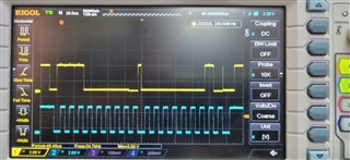
    Here a photo of control register write "1" @90Khz clk

    Regards,

    Jo

  • No delay should be needed. But is it possible that the accesses without delay did not generate the stop condition?

  • Possible, I have to check the atmel avr I2C library I am using..

  • It is not bit-banging though, I am using the mcu pheripheral

  • lib polls for stop condition- good chance that it hangs there forever, without timeout gards

  • The lib issues start and stop conditions by setting the relevant flags in the pheripheral I2C control register. Perhaps there are timing requirement between stop and next start conditions

  • Jo,

    Don't worry about wasting time this is what I'm here for.

    I don't remember if you have done this test already, but if you disconnect the LDC1614 from the TCA9548A and you keep the pullups, do you see data on the other side of the TCA9548A when you don't use a delay.

    If the TCA9548A is properly able to read back that the channel has been selected then it is simply a passFET in that state and any information on one side should propagate to the other. There is just no way for the TCA9548A to not send that data through unless the channel has not been switched on. I highly doubt that is the case if you are able to properly read that the channel was selected.

    I think what you are talking about above is more likely that the library you are using when you try to send another command without a delay never sends a stop bit but I would still expect to see the address byte propagate through at least. Does any data get through when you send a read command.

    Best,

    Chris

  • Hi Chris,

    I will do that additional test asap- thanks for your deeper investigation.

    I am using I2C only rarely, so my knowledge of the protocol is at very basic level. What I found in the I2C
    specification regarding timing constrains, is that the timing depends on the bus speed, at least in following
    instance:

    Bus free time (min. time between stop and next start) for 100Khz: ~4.7 uS, but at 400Khz it is 1 uS.
    Perhaps quite possible that at 10Khz it is much longer. I think I have violated that constrain.

    After code examination of the library, I am sure that I2C transactions can hang at many places because there are no
    timeouts implemented. Basically, the lib is initiating  start/stop conditions be manipulating some flags in the MCU
    I2C control register. After that, the lib is just polling those flags, waiting for toggling which would indicate the
    MCU has accepted a start or stop condition. Maybe something went wrong there, to investigate that further,
    I would probably need to check each and every error code of the status register.

    Regards,
    Jo

  • Just show an oscilloscope trace of the old code. (A stop condition is a rising edge on SDA while SCL is high.)

  • Will do it with logic analyzer asap.

  • Hi Chris, Hi Clemens.

    I would like to take it step by step and have set up logic analyzer to my simplified hardware test setup, as in photo posted earlier.
    (MCU <==> TCA9548A <==> LDC1614).

    LA connected to SCL, SDA, SD0, SD1

    For the test I was not doing any LDC1614 access, just control register write / read with TCA9548A.

    Strange (or perhaps normal) observation:

    write / read without delay in between (except those caused by the I2C api written in C): No activities on SD0, SC0
    write / read with added delay about 25 us in between, then activities on SD0, SC0:

    Regards,

    Jo

  • The LA shows that there is no stop condition ("P") between the accesses.

    Apparently, your I²C software (or hardware) automatically omits the stop when there is a following I²C transaction. This is allowed by the I²C specification, but not helpful with the TCA9548A. Which library are you using?

  • It an old library of Atmel (Microchip) AVRs, called Fleury TWI library

  • Below my wrapper functions, calling directly the library function. I am not aware of repeated
    start conditions there, but I will check the library asap.

    uint8_t readControlRegister(uint8_t i2cAddr)
    {
    uint8_t result=0;
    startTwi (i2cAddr, TWIM_READ);
    result=readNackTwi();
    stopTwi();
    return result;
    }

    void writeControlRegister(uint8_t i2cAddr, uint8_t val)
    {
    startTwi (i2cAddr, TWIM_WRITE);
    writeTwi(val);
    stopTwi();
    }

  • There is a "P" in the trace with long delay of 25uS between write / read. 
    Then the other case violates min. bus free time, could that be? 

  • Hello,

    This problem is fixed now- there was an error in the library code I am using, polling the wrong flag on stop condition issued.
    Surely this will not be the case with the original library, but I will double-check it.

    Regards,
    Jo

  • And thank you very much for checking.

  • That is great to hear Jo. Let me know if you need anything else.

    Best,

    Chris