This thread has been locked.

If you have a related question, please click the "Ask a related question" button in the top right corner. The newly created question will be automatically linked to this question.

DS90UB933-Q1: Currently trying to use the customer's 914 board to connect with the 933camera, but the camera cannot light up

Part Number: DS90UB933-Q1

Hi Team,

I think 933 & 913 is pin to pin, in theory it should be exactly the same, cause according to the theory, 933 and 914 can be connect !

But currently we try to use the customer's 914 board to connect with the 933 camera, but the camera cannot light up!

The possible reason is that the CLK of the sensor of TI933 is sent by 933? or something need to reconfirm ?

933 camera link

https://www.leopardimaging.com/product/autonomous-camera/ti-fpdlinkiii-cameras/li-isx019-ti933/li-isx019-ti933-110h/

Customer's 914 board SCH

OTODAS303_C01_TI914.pdf

  • Hello Kygo,

    The 913A and 933 parts are p2p compatible. They also have the same register structure and default register values. The only difference is each device's supported PCLK frequency at each mode of operation:

    913A

    933

    In the 913A/933 devices, the PCLK from the sensor is fed into the serializer and used to drive the serial link and establish LOCK with the deserializer. But this should be done when the camera powers-up. As long as the camera powers-up and sends a PCLK within the allowed ranges in the 933 datasheet and within jitter specifications, then the 933 should be able to establish LOCK with the deserializer.

    I have a couple of follow-up questions:

    1. Did customer test a setup where they connected a 913A serializer to the customer's 914A board?
      1. Is the 914A able to connect to other 913A system, with no problems?
    2. Could you clarify what it means when you say that the camera cannot light-up?
      1. What is the expected result vs what you are actually experiencing?
    3. Are you able to establish LOCK between the 933 and 914A FPD-Link devices?

    I will look into the provided materials in more detail and provide comments. 

    Best,

    Justin Phan

  • Hi Justin

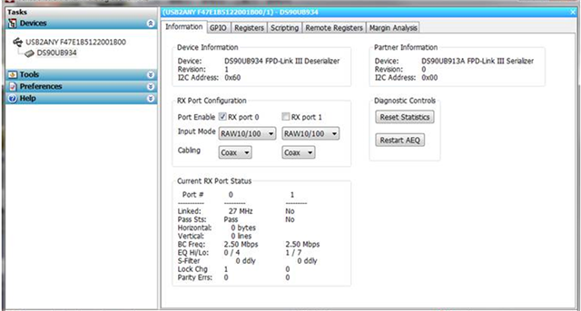
    At present, we have connected with the DS90UB934 EVB. Judging from the light signal on the EVB, there is a Lock, but the I2C Address cannot be read. ( DS90UB934 EVB connect Leopard 933 camera )
    The measured PCLK is 54.59MHz (as shown in the figure below), and the Camera does not seem to operate normally.

    The following image is the information captured by the Analog LaunchPAD tool

  • Hello Kygo,

    1. Just to clarify, is the measured PCLK signal from the 933 in the Leopard Image Sensor?
      1. If there is no PCLK signal being sent into the 933 or the PCLK input does not meet the specifications for jitter, rise/fall times, etc... defined in section  Recommended Serializer Timing For PCLK in the 933 datasheet, then the internal clock in the 933 device is used to drive the channel connection. This connection is used to ensure I2C commands can be sent between the SER/DES devices, but video data will not be transferred if the internal clock is used. If the PCLK input into the 933 is valid, then the line rate will be driven by PCLK and video data transfer will be possible. In both scenarios, LOCK will be HIGH, but video data transfer will only be possible if PCLK input to the 933 is valid.
    2. If you are connecting a 934 EVM to the 933 in the Leopard Imager, then can you confirm that the MODE settings on the 934 EVM match the ones on the 933?
      1.  Also confirm the jumpers match the desired setup and that PoC is enabled. Also make sure the BISTEN pin on the 934 EVM is pulled LOW.
    3. Can you provide a register dump of the 934?
    4. Can you also read register 0x4D in the 934 EVM multiple times, and confirm that the LOCK_STS bit is always set to 1 and the LOCK_STS_CHG bit is constant at 0?
    5. Can you run the Margin Analysis tool as well and post the results?

    Best,

    Justin Phan

  • Hi Justin

    After discuss with RD

    From experience, the PCLK measured on the 934 is not from the 933
    If it comes from 933, theoretically 933 and 934 should have established communication, then I2C will communicate with each other.
    If there is a connection, the software will automatically obtain the I2C address of the 933, but this lens cannot capture the I2C address

    We have tried it, AR0231+TI913 camera can automatically obtain the I2C address, and the measured PCLK is 99MHz

  • Hello Kygo,

    If there is no PCLK input to the 933, then the 933 will use its internal oscillator to drive the channel and allows I2C communication between the connected 933/934 devices. But in this mode, video transfer will not be possible. If there is PCLK input to the 933, but the PCLK is not meeting jitter or other requirements, then the 933 may be constantly switching between using the internal oscillator and PCLK input to drive the Forward Channel link, which will result in unstable LOCK and may cause I2C commands to be lost.

    1. Can you perform some of the reg dumps and tests that I mentioned in my previous post, such as reading register 0x4D on the 934 EVM multiple times and checking to see if the LOCK_STS_CHG is constant at 0, and post the results?
    2. Are you able to directly measure the PCLK signal being inputted to the TI933 device and confirm that the signal meets the datasheet requirements?
      1. Section 6.6 Recommended Serializer Timing For PCLK in the 933 datasheet for more details.

    Best,

    Justin Phan

  • Hello Kygo,

    I have reviewed the provided 914A schematic. Attached are my comments.

    OTODAS303_C01_TI914 - Reviewed.pdf

    Customer should confirm that the Power-Up Sequence is followed on the 914A and that the TI933+Camera is also powered-up correctly. Also make sure that the MODE settings are correct. I see two 914A devices in the schematic. Make sure you are connecting the Leopard Imager to U27, since that is the one that seems to have the matching MODE.

    If customer can confirm all of the devices are powered-up correctly, then the next step would be to focus on providing a register dump of the 914A for further debug. 

    Verify if LOCK is stable, by repeatedly reading register 0x1C on the 914A or monitor the LOCK pin on the 914A to see if it can stay consistently HIGH.

    Other steps that can be done in parallel is to measure the Insertion Loss, Return Loss, and Impedance on the high-speed signal traces on the PCB boards and the cable to see if it meets the required channel specifications. See App Note SNLA229 for more details. It would also be a good idea to verify that the PCLK input into the 933 serializer in the Leopard Imager is meeting the requirements defined in the 933 datasheet.

    Best,

    Justin Phan