This thread has been locked.

If you have a related question, please click the "Ask a related question" button in the top right corner. The newly created question will be automatically linked to this question.

DP83826E: DP83826E

Part Number: DP83826E

Hi,

We are having link loss issues on an ethercat system, and are having a really hard time figuring out what is going on.  We have been trying to figure this out for over 2 weeks of troubleshooting.

We have been integrating an ethercat motor controller family for 5+ years from a well known motor control manufacturer.  We have designed countless carrier boards with the same ethercat magnetics circuit that have been proven to work reliably in many designs.  This manufacturer eventually had to change their ethercat PHY chip due to chip shortage.  They migrated from the KZS8081 to the DP83826E.  We recently have discovered that installing any of the newer motor controller modules using the new PHY (DP83826E) into our newest carrier boards result in non-functional ethercat, due to periodic link loss.  Installing the older motor controller modules (KSZ8081) into the same carrier boards result in functional, reliable ethercat.

We have no access to the phy itself since it is buried in the motor control module sandwhich, and we have no access to the motor control manufacturer's schematics or firmware.  I figured out which PHY's they were using by cutting open two motor controllers from older and newer serial number groups.  The manufacturer has not responded to any of our technical inquiries so far on this issue, and we have 50+ of these drives purchased already, and very few drives left with the old PHY.  We are in great need to resolve this link loss issue.

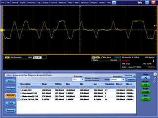
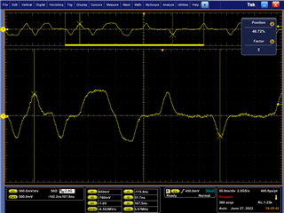
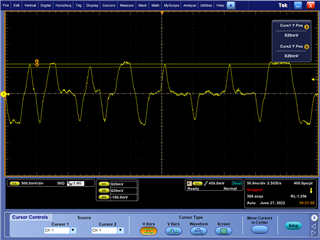
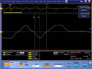
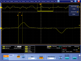
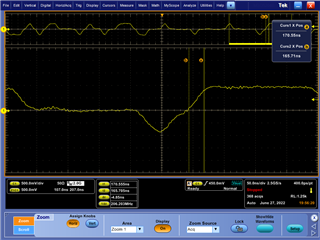
We have scoped the ethercat signal integrity using a 2GHz Tek 5024 oscilloscpe with 3.5GHz differential probes, and feel the signal integrity looks good even on the boards with the DP83826E.  The best I can see is that the MLT train from the MDI pins will just cut out.  I don't know what is causing the link loss.

Can you list potential problems that would cause link loss in relation to the DP83826E itself?  Could this be related to the type of magnetics we are using?  Would logging the ethercat frames on profishark (includes crc error frames) show us why a link would drop?  How can I packet sniff and decode the encoded MLT pulses coming out of the MDI port on the phy directly to identify why the link is dropping?  Are there any tools I available I can use to do this?  If there is a way to decode it, I can identify if the link losses are happening randomly, or if they are happening as a result of a particular repeating communication incident.  Discovering the reason for the link loss is the key behind understanding and fixing our problem.

Any help that can be provided would be of enormous help for us. 

Thanks,

Kevin Wood

  • Hi Kevin,

    There are a myriad of reasons that could cause a link loss issue including magnetics, other schematic errors, layout issues, incorrect register configuration, EMC, cable type, etc. Unfortunately this is extremely difficult for us to debug, unless you can provide a schematic or register dump. Can you provide either of these? 

    We do have a KSZ8081 to DP83826E rollover document here which may or may not be of assistance. 

    Ultimately, this sounds like the responsibility of the motor controller manufacturer to debug. 

    Thanks,

    David

  • We managed to get a hold of the manufacturer and talk with them.  We also were able to do some more troubleshooting that got us much farther.  We have determined that the magnetics we have successfully used for 4+ years on 12+ board designs for ethercat no longer work with their new PHY selection DP83826.  We removed the TDK magnetics, ALT3232M-151-T001 and ACM2012-201-2P-T001, and jumpered in an RJ-45 magnetics module A63-113-431P112 which works fine.  We now know that the KSZ8081 worked fine with these TDK magnetics part numbers, but the DP83826 does not.  What types of things should we be looking for that would help us identify why this phy does not work with these magnetics and other PHY chips do?  Is there anything about this PHY or magnetics that could cause it not to work? 

    1.  We are going to work on trying to get a diff between the frequency response of the old magnetics vs the new magnetics.

    2.  These TDK magnetics are 150uH vs most ethernet magnetics are 350uH.  Does the DP83826 have enough drive strength to properly drive these magnetics, and could there be a problem there?  I know the DP83826 is a voltage mode driver vs others like the DP83822 are class a or class b current drive.

    3.  What voltage thresholds should we be checking for on the signal that would cause this DP83826 PHY to break link?

    4.  Is there a particular slew rate we should be looking for?

    5.  At the PHY's most basic logic level, what types of registers/functions actually drive the link status to go inactive?  In the chip itself those methods are deterministic.  I want to explore every possible reason that the link is breaking.  Even with the bad magnetics, I was able to confirm that both the Ethercat Master and the motor controller are broadcasting the 100BASE-Tx option in auto-negotiation on their MDI ports.  There is a small ~5-15 second period of communication and then the link drops.

    Any help is much appreciated.

    Thanks,

    Kevin

  • Hi Kevin,

    This inductance is likely the issue. I am surprised these magnetics worked with the KSZ8081, since that part also specifies a minimum of 350uH. 

    The only data we have is with 350uH magnetics, we have not tested 150uH magnetics with the DP83826. The device is guaranteed to operate with any of the transformers listed in Table 12-1 of the datasheet. 

    Would love to see the frequency responses of new vs old magnetics.

    Another option to compare the effects is to conduct compliance testing, using a Tektronix scope for example. The following tests will show us if the device is IEEE compliant with each magnetics. 

    Thanks,

    David

  • I will make sure that we get some frequency responses of the transformers circuits as part of our troubleshooting list.  I probably can't do this until next week. 

    Another test that we have done, is that when we take the same transformer and solder 6" wire leads from the transformer footprint to the transformer remoted off the board, it also works fine.  Does this support the theory that the inductance is too low?

    Also, if this is an inductance issue, is this because the drive strength of the PHY is too weak to get the voltage swing needed for ethercat?

  • Also, we have confirmed that the manufacturer uses the next size up in magnetics on some of their designs, and has been put through EMC testing.

    ALT4532M-201-T001.

    product.tdk.com/.../info

    This is also not 350uH.  Does this still seem like the inductance is too low?

  • Also, we are only using common mode chokes on the cable side of the transformer.  Would adding common mode chokes on the PHY side of the transformer help the load inductance? 

  • Hi Kevin,

    I cannot provide a precise theory for why some magnetics are operating fine with additional wires. All I can say is the device has been tested with the magnetics listed in table 12-1 of the datasheet, and is guaranteed to meet compliance specifications with these components. Using other components, I cannot guarantee any operation, but you are welcome to find and use what works. 

    The common mode choke location should not matter.

    Thanks,

    David

  • We are working on a test board with various magnetics to make sure we are going to select the best choice for both signal integrity and packaging.  We have extremely tight packaging constraints.

    Here are some screenshots of some signal analysis from one of the pairs of the PHY.  I would appreciate additional input on these signals.

  • After looking at the amplitude measurements generated by the TEK tool, I feel those measurements don't represent the overall waveform that well.  When I use a cursor, the peaks of the pulses are in the 1.28V-1.32V range.  That doesn't seem like something that would generate a link drop to me.

    I am seeing that the rise and fall times are around 1-1.25ns when it should be 3-5ns.  This sounds like this would improve by changing to a higher inductance transformer.

  • I took another data set later, and didn't even power cycle the equipment, and took the data off the same pair.  Now it was showing reduced amplitude, rise and fall times and slew rates.  I am wondering if this could all be a result of overloading/current starvation of the output driver?

  • Hi Kevin,

    I cannot diagnose a raw waveform. If you would like to verify the waveform is conforming to IEEE compliance specifications, please use Tektronix's compliance software. 

    Thanks,

    David