


Part Number: DP83822IF
Other Parts Discussed in Thread: DP83822I,
Hi team,
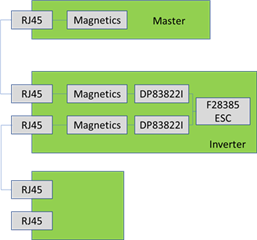
Previously my customer developed an inverter project with TMS320F28385+DP83822I, where two DP83822I(100BASE-TX) acts as Ethercat. The system structure as below. The system can work well and has good communication between master and inverter.
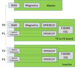
Recently they kicked off a new project with interface changed to optical transceiver. The system structure is changed to following picture. Because the master only has electric interface, TX to FX board is added to transform electric signal to optical signal.Phy and its peripherals are nearly the same as the old project except the optical transceiver. And the software is also not changed. Customer found that master can communicate with P0 smoothly but the communication between P1 and P2 failed.
We found some obvious mistakes on customer’s schematic diagram and made some changes.
- Connect the SD pin of optical transceiver with pin24 of DP83822IF and pull up to 3.3V; (You can find the DS of optical transceiver as attached)
- Change the P2 from mode 4 to mode3, P3 from mode1 to mode2 in order to enable 100BASE-FX.
- RX_ER of P1 and P2 is pulled up and set to mode 4.
- SD is active high.
After changing above items, communication between P1 and P2 failed again. Could you help review that and give some suggestions to solve this communication problem? Customer didn’t change their software in new project at all. Should they change some registers? There is no capacitor between PHY and optical transceiver and customer just connect the wire directly, will it be the root cause?
