This thread has been locked.

If you have a related question, please click the "Ask a related question" button in the top right corner. The newly created question will be automatically linked to this question.

DS90UB936-Q1: some questions about 936

Part Number: DS90UB936-Q1
Other Parts Discussed in Thread: ALP

Hi team,

  1. For UB936 power up sequence, why need to hard reset like below figure?

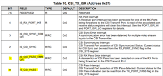
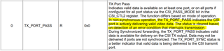
  1. What is the meaning of 0x37 bit 0 and 1? If they are both set, what is the meaning?

BR

Jiawei

  • Hello Jiawei,

    1. The Power-Up Sequence figure is meant to convey a lot of information. The "Hard Reset" is not required as part of the device power-up. If VDD_SEL=LOW, then you just need to make sure VDD18 and VDDIO are pulled to a stable HIGH before PDB, within the timing defined in the datasheet. If the customer would like to perform a "Hard Reset" on the 936 device, then they would need to wait at least T7 seconds after PDB has pulled HIGH and the PDB pin needs to be pulled LOW for at least T8 seconds to perform the "Hard Reset".
    2. Register 0x37 is the Interrupt Status register for the CSI-2 TX Port. If the Interrupt Service Routine is enabled in register 0x36, then the INTB or GPIO pins will send a signal to the processor to indicate that an interrupt condition has occurred. The corresponding bit in register 0x37 will be set as well and the user needs to read register 0x37 to clear the bit and clear the interrupt. See Section 7.5.8 Interrupt Support in the 936 datasheet for more details.
      1. Register 0x37[0] is an interrupt condition where the bit will be set HIGH if the TX_PORT_PASS bit status is changed from LOW->HIGH. TX_PORT_PASS is a status bit that indicates that valid data is available on the CSI-2 TX Port and that the CSI-2 TX Port is outputting video data.
      2. Register 0x37[1] is an interrupt condition where the bit will be set HIGH if the TX_PORT_PASS bit is changed from HIGH->LOW. This means an interrupt has occurred because the CSI-2 TX Port is no longer able to detect valid data to output and has stopped outputting video data.
      3. Both bits can only be set by enabling the interrupts in register 0x36. If both bits are set, then that means that the TX_PORT_PASS bit went from LOW->HIGH and HIGH->LOW before the user cleared the bits. Note that register 0x37[1:0] are cleared on read and will maintain their status until the user reads the register through an I2C write.

    Best,

    Justin Phan

  • Hi Phan,

    Thanks for your reply. Could you kindly tell me how to fix AEQ? Just configure 0xD4? Is there a configuration order? And how to check we have configure right?Thanks!

    BR

    Jiawei

  • Hello Jiawei,

    On the 936, the AEQ will loop through a default range of EQ and Strobe settings in order to recover the data being sent from the SER->DES. Typically, customers do not need to configure the AEQ, since the AEQ will recover the serial data through a range of aging and temperature conditions.

    Are you unable to achieve a stable LOCK between your 936 and serializer device?

    You could run the MAP tool on ALP to check the quality of your channel link between the SER->DES and adjust the AEQ settings in the 936, by referencing the following App Note:

    https://www.ti.com/lit/an/snla301/snla301.pdf?ts=1655911100628&ref_url=https%253A%252F%252Fwww.ti.com%252Fproduct%252FDS90UB954-Q1

    But this is typically a temporary fix and customers may find difficulties in achieving passing performance across multiple devices in production. We actually recommend reviewing the Insertion Loss, Return Loss, and Impedance of the channel link and making improvements in the system design to achieve stable LOCK, without needing to modify the default AEQ settings.

    Best,

    Justin Phan

  • Hi Phan,

    Thanks for your comments here, We do meet unlock issue in 933>>936. For unlock issue, could we have another debug direction expect margin analysis? But I also want to understand how to fix AEQ, could you kindly also give the answer here? Thanks!

    BR

    Jiawei

  • Hi Jiawei,

    1) Just to clarify on the unlock issue, do you mean that when you read register 0x4D on the 936 multiple times, do you see the LOCK_STS_CHG bit constantly changing?

    In a stable LOCK situation, we expect to see the LOCK_STS bit set to 1 and the LOCK_STS_CHG bit remain constant at 0 after multiple register reads to register 0x4D.

    2) Could you also run the MAP tool in ALP on the 936 and post the results?

    There is typically no issue with the AEQ on the 936 device itself. If the 933->936 are frequently LOCKing and unLOCKing, then this is likely a system-level issue and we recommend making improvements in the design. Could you first answer the above 2 questions, so that we can determine a debug direction?

    Best,

    Justin Phan

  • Hi Phan,

    1. We used oscilloscope to monitor lock pins (mapped to port1 through 0x0C) and found unlock, see attached video.
    2. I asked customer do it and need customer feedback.

    As customer are really push on this, I think we need more directions, thanks!

    BR

    Jiawei

  • Hello Jiawei,

    1. I don't see an attached video, but if you can confirm that the 933->936 pair are continuously going through LOCK/unLOCK, then that means the AEQ on the 936 cannot reliably recover the serial data being sent by the 933 SER. This is likely caused by reflections or signal integrity issues in the high-speed channel between the SER->DES devices. I recommend reading register 0x4D in the 936 device multiple times, in order to confirm.
    2. The first debug step would be to run the MAP tool on the 936. This gives us a high-level overview of the channel link quality. If the results are not too bad, then it may be possible to fix the issue by adjusting the AEQ settings on the 936. But we recommend improving different aspects of the system-level design, in order to make sure that channel requirements are met and that the AEQ can recover the serial data without needing to modify the AEQ settings in all systems produced.
      1. Can your customer also measure the Insertion Loss, Return Loss, and Impedance of the high-speed signal traces on the 933 PCB board, the cable, and the 936 PCB board?
      2. The required S-Parameter and impedance requirements for the high-speed channel on each PCB board is defined in Table 227 in the 936 datasheet. Make sure to verify that each PCB board can meet those requirements. If a PCB board cannot meet the IL/RL/Impedance requirements, then we would need to review that PCB board's schematic and layout, to see what improvements can be made to meet the channel requirements.
      3. We also have a more detailed breakdown of the cable and entire channel's requirements, but that information is under NDA. We also have some test procedure documentation, but that is under NDA as well.
      4. Does your customer have an active NDA with TI, which convers FPD-Link parts?

    Best,

    Justin Phan

  • Hi Phan,

    Thanks for your reply. Could you kindly also check 936 code? Any questions pls let me know!

    BR

    Jiawei

  • Hello Jiawei,

    A few comments:

    1. Are you writing registers on the 936 deserializer device? 
      1. There is a line that writes to register 0x32, but this is a RESERVED register in the 936 datasheet. Do not write to RESERVED registers.
    2. I believe you are connecting a 933 to the 936 deserializer. When connected to a parallel-interface serializer, the 936 has a feature to assert a minimum FrameValid time, in order to prevent false detection of FrameValid, which is done in register 0xBC in the 936.
      1. Why did customer set register 0xBC in the 936 device to 0? Recommend to keep this value to the default value of 0x80 to prevent false detections of Frame Valid.
    3. There is a line that sets register 0x4C = 0xF. This command writes to RESERVED registers in the 936 and it is recommended not to do this. Only write to public registers listed in the 936 datasheet.
    4. I am not clear on your desired Frame Rate for the Internal FrameSync signal, but if you are connected to the 933 serializers, then the Back Channel rate will be 2.5Mbps and the BC frame period will be 12us. Make sure to follow Section 7.4.27.2 Internally Generated FrameSync in the 936 datasheet to set registers 0x19-0x1C to the correct values.

    Best,

    Justin Phan

  • Hi Phan,

    Thanks for your reply. I met another black issue (won't recover until power off and power on) and at this moment lock is high and 0x73-76 are stable. Below is the registers dump of abnormal (left) and noraml (right).

    • About 0x37 bit0, bit1, you said 'Both bits can only be set by enabling the interrupts in register 0x36'. But from the register dump, we can see 0x37 bit0, bit1 both set while 0x36 is 0x00, could you kindly tell me the reason? And at this moment, TX_PORT_PASS bit is set, why 0x37 bit1 is set?
    • Can we make sure CSI port has valid video data if 0x35[0] is set? If 0x35[0] changed one time, will the display be black continuelly?

    For the black issue, could you also kindly share your comments and debug directions here? Appreciate!

    BR

    Jiawei

  • Hello Jiawei,

    1. I looked through the datasheet again and found one sentence that explains why bits in register 0x37 are set, even though register 0x36 is set to 0x00.
      1. Setting bits in register 0x36 will enable the device to send an interrupt signal to the INTB pin or GPIO pins. It will also set the appropriate bits in register 0x37 based on what interrupt has occurred. But even if register 0x36 is set to 0x00, then the bits in register 0x37 will still be updated to reflect interrupt conditions that occur. The only difference is that now no interrupt signal will be generated on the INTB or GPIO pins.
    2. If register bit 0x35[0] is set, then that means that video data is being pulled from the RX Port buffer and being sent to the CSI-2 Output Port. If register 0x35[0] = 0x00 or if register bits 0x37[1:0] = 0x03, then that indicates that the 936 is put in a situation where it is unable to pull video data from the RX Port buffer and output it on the CSI-2 output port.

    The only difference between the abnormal and normal scenarios is that register 0x37=0x03 in the abnormal situation, but register 0x37=0x00 in the normal situation. There are no errors detected at the RX Port on the 936 and LOCK does seem stable. 

    1. You mentioned that this black screen issue is recovered when you power off and power on.
      1. Are you powering off/on the entire system, or only the FPD-Link 936 chip? Could you clarify what is being power cycled?
    2. Is there an initialization script that is run at power-up, which sets the registers in the 936, the connected serializer, and the camera?
      1. The I2C_PASS_THROUGH bit is not set in register 0x58, which means that the processor cannot send I2C commands to the remote camera.
      2. Can you verify that the camera is powered-up correctly and has the proper registers programmed?
      3. Can you also make sure in the initialization script that LOCK is stable, before sending any I2C commands from the Processor to the connected serializer and camera?
    3. RX Port 1 is enabled in register 0x20 and Round-Robin Forwarding is enabled in register 0x21, which means that the 936 will pull data from RX Port 1 as it becomes available in the video buffer and forward it to the CSI-2 TX Port. If video data can't be forwarded, then 0x35[0] will be set to 0. If video sporadically becomes available, then register 0x35[0] may be set to 1 in the register read, but register 0x37[1:0] will catch the change. 
      1. In the abnormal case, can you verify that the FPD-Link device's Power-Up Sequence was followed properly and that the camera is actually sending a stable stream of video data?

    Best,

    Justin Phan