This thread has been locked.

If you have a related question, please click the "Ask a related question" button in the top right corner. The newly created question will be automatically linked to this question.

TMDS251: HDMI Switch Design Problem

Part Number: TMDS251

Hello,

I need to inquire about this DVI/HDMI Switch. 

In my case, there are two HDMI sources from different connectors, they are to be transmitted to the display.

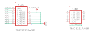
There is no use of a Micro-controller in my design, all VCC, VDD, SELECT pins are supplied with respect to the datasheet, from the regulated voltage supply on the board etc.

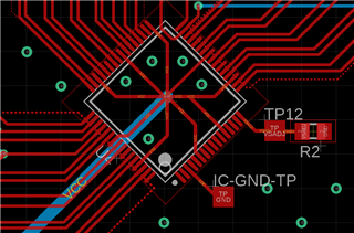
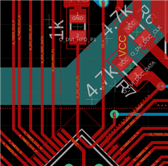
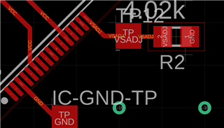
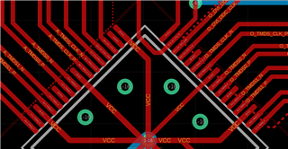
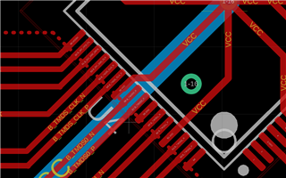
The layout was made according to the Figure 18. on the datasheet.

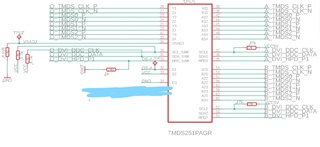
The S1 pin no. 32 (OE-A in the images) is being supplied from an external logic signal. H:3,3 V L: 0,4 V. And S2 pin no. 33 (VCC in the image) is supplied with 3.3 V at all times.

In the testings we are measuring all pins at the desired states, however we could not get image on our display. (VSADJ : 1,23 V)

Is this IC requires presence of an Micro-controller for operating?

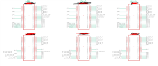
The images of the layout can be found attached.

Would appreciate your help. Kind regards.

Ata

  • Ata

    Can you please share your schematic? Are you seeing the 5V coming from the source and if the 5V is present, are you seeing the display driving HPD high back to the source?

    Thanks

    David

  • Hi David. Thanks for your reply.

    HPD from the source (pin no 50 in the image "B_DVI_HPD_P1") is 5V. But the HPD to the Display (pin no 31 in the image "O_DVI_HPD_P1") is 1,2V.

    The OE-A pin is the control signal of my system, for the given measurements the OE-A pin was in logic low state(0,4V).

    Unfortunately I cannot share the whole schematic but the corresponding parts are attached. Hope this helps.

    Waiting for your reply. Thanks.

    Ata 

  • Ata

    If you switch the OE-A pin to high, are you then able to see B_DVI_HPD_P1 goes low, and A_DVI_HPD_P1 goes to 5V? This is to verify the HPD functionality.

    With HPD checked out, and with OE_A goes back to 0V, can you please probe the SDA_SINK/SCL_SINK and SCL2/SDA2 to see if I2C data is going across them? You can use either a scope or an I2C analyzer for this.

    Thanks

    David 

  • Hi David,

    for the first question, yes HPD functionality works just fine. We get A_DVI_HPD_P1 high and B_DVI_HPD_P1 low.

    for the second question, unfortunately I am unable to probe those signals.

    Is there anything else you could suggest?

    Thanks.

    Ata

  • Ata

    If you can't probe the SDA_SINK/SCL_SINK and SCL2/SDA2, can you probe the TMDS_CLK on both sides of the TMDS251? Since HDMI is a 3.3V DC-coupled interface, you would need to provide 50ohm to 3.3V termination on the scope when probing the clock.

    Thanks

    Davi