This thread has been locked.

If you have a related question, please click the "Ask a related question" button in the top right corner. The newly created question will be automatically linked to this question.

SN65DP159: HDMI DEBUG ISSUES - Detection Solution in HDMI Sink

Part Number: SN65DP159
Other Parts Discussed in Thread: TMDS181

Hi,

We have board lets call it TPG(Test Pattern Generator board) that include FPGA that transmit constant pattern(it doesn't need HPD/I2C/CEC etc.) and routed to equalizer and from equalizer(from another company) to HDMI connector - this is the source side.

Here is the part of the schematic from the TPG side:

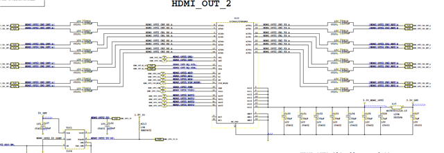
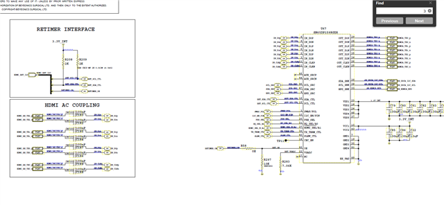
In my board that Im using lets call it PB this is the sink side, the signals comes from HDMI connector (the TPG is connected to my board trough HDMI cable) and routing to TI RETIMER :SN65DP159RGZR

Here is part of the schematic(with not include the HDMI connector ):

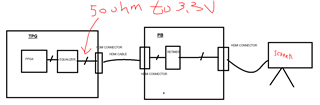
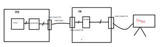
simplified block diagram :

The problem: 
in the PB - at the output of the Retimer there is a connection to the screen with another HDMI connector,
and the screen does not RECIEVE the video that the TPG transmits,
but if for example I take the cable that is connected to the TPG and connects to the screen directly(see some video) then back to my PB card,
suddenly the signals are received properly and I see them on the screen.
I would expect that if there was a problem of detection then it will continue to be,
it is important for me to note that there is no HPD and it is not even connected at all on the side of the TPG. It seems that the equalizer does not recognize the retimer.
This is an HDMI 2.0 broadcast what could be the problem?
if you need any information Ill attach it ,
thanks.
  • Hi,

    Can you please show the full connection of the DP159? 

    I notice the OE pin has a 10k pulldown, can you remove R58 and replace R297 with a 0.22uF capacitor? This will create a passive reset circuit that will satisfy the DP159 power up sequence requirement. 

    but if for example I take the cable that is connected to the TPG and connects to the screen directly(see some video) then back to my PB card, suddenly the signals are received properly and I see them on the screen.

    Are you saying that if you connected the TPG directly to the screen, then you are able to see the video? In this case, does the equalizer output support AC coupling cap that is required by the DP159? If not, do you have 50ohm to 3.3V termination between the equalizer output and the AC coupling capacitor as shown below,

    Thanks

    David

  • Hi David,

    1. OE is controlled by internal FPGA in the PB, so in start condition it pull-down to 0 that turn it off (I tried connect the cable after all the voltages in PB rise up , and try it before they rise up , no change, tried a lot of combination) , you still recommend to try your advice?

    Are you saying that if you connected the TPG directly to the screen, then you are able to see the video?  - Exactly. and then unplug the cable and connect to PB and magic happen and it works.

    2. At the first picture you can see I have only AC-Coupled capacitor , no termination to 3.3V, but I expect when I connect the cable from TPG to PB the termination in DP159 will be felt by the equalizer (DP159 contain 50ohm internal termination connected to VBIAS )

    what's next?

    Thx.

  • Hi,

    The HDMI is a 3.3V DC-coupled interface, I am suspecting the equalizer output is expecting to see this 3.3V common mode voltage because when the TPG is connected directly to the screen, the equalizer sees the 50ohm termination to 3.3V in the screen and then enables its output. 

    But with the AC-coupling between the equalizer output and the DP159, the AC coupling capacitors blocks the DP159 common mode voltage. This is why I propose to add the external 50ohm to 3.3V termination to properly biased the equalizer output. The DP159 Vbias is also 0.7V, not 3.3V.

    You can probe the equalizer output directly with and without the 50ohm to 3.3V to see if adding the external 50ohm termination will enable the equalizer output.

    Thanks

    David 

  • Hi David,

    Before I tried to solder 50 ohm termination, I have 3 questions:

    1. Is there a possibility that you are familiar with configuring the DP159 mode where the TDMS will go through it directly and then the equalizer will feel the screen?

    2. If we go to solder termination to 3.3v is enough for clock signals or to all TDMS signals(RGB and CLK)? 

    3. What about TMDS181 ? what is his VBIAS? his value not mentioned in the datasheet...

    Thanks

  • Hi,

    Please see my inserted response,

    1. Is there a possibility that you are familiar with configuring the DP159 mode where the TDMS will go through it directly and then the equalizer will feel the screen?

    *** No, there is no bypass mode in the DP159 for the TMDS to go through it.

    2. If we go to solder termination to 3.3v is enough for clock signals or to all TDMS signals(RGB and CLK)? 

    *** You would need to provide 50ohm to 3.3V termination on all three TMDS data lanes plus the clock lane. But you can start with the clock lane and see if you can see the clock coming out of the equalizer with and without the external 50ohm to 3.3V. 

    3. What about TMDS181 ? what is his VBIAS? his value not mentioned in the datasheet...

    *** If the equalizer output requires to be DC-coupled, then the TMDS181 is a better fit for this design since TMDS181 is designed for DC-coupled input with its VBIAS at 3.3V. I recommended the 50ohm to 3.3V termination with DP159 because I think it will be easier to populate the resistors than replacing the DP159. 

    Thanks

    David