This thread has been locked.

If you have a related question, please click the "Ask a related question" button in the top right corner. The newly created question will be automatically linked to this question.

DS90UB960-Q1: DS90UB960-Q1

Part Number: DS90UB960-Q1

We have 4 camera in for FPD link3 of DS90UB960.

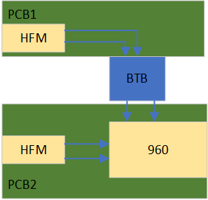
2 FPD link3 and 960 are on the same PCB,but other two FPD link3 are on other PCB by BTB connector.

BTB connector support up to 16Gbps.

1.What is risk for this design? FPD link3 is connect by BTB in product.

2.What insert loss is requirment at PCB and BTB connector?

2.What is place about POC and ESD at PCB1 or PCB2?

  • Hello,

    The primary concern from an FPD-Link point of view would be the effect on insertion loss and return loss.  

    1. You will need to make sure the channel can still meet our requirements for insertion loss and return loss.  You can view these numbers in the channel requirements section of the 960 datasheet.

    2. Again these values are in the datasheet in the channel requirements section.

    3. For PoC considerations you will need to ensure the connector can tolerate the current you are trying to send over the cable. Additionally you should make sure there isn't significant IR drop across the connector.  ESD protection spec will be the same but you may be adding an additional point for an even to occur.  It will need to be determined at a system level if external ESD protection is required.

    Regards,

    Nick