This thread has been locked.

If you have a related question, please click the "Ask a related question" button in the top right corner. The newly created question will be automatically linked to this question.

THVD8000: Ground to the earth : one wire communication

Part Number: THVD8000
Other Parts Discussed in Thread: THS6222

Hello,

I recently bought 3 EVM of the THVD8000 to test the component in order to implement it on our products.

The first tests without connecting to the GND of the power supply to the earth went well, but when I tried to connect the GND to the earth it obviously stopped the communication between the modules.

Here is the model I tried :
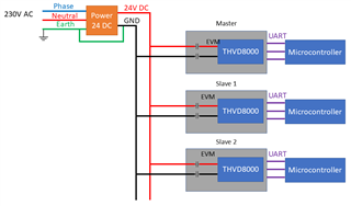
And I have seen this thread that represent a similar implementation (24V DC power supply and data, up to 64 nodes, up to 80 meters, and the maximum data rate possible) that I would like to do with the only difference that the GND of the power supply must be connected to earth.

Also I saw on the answer that it was possible to connect the GND of the power supply to the earth but the communication would be only with one wire.

Do you have more documentation or information about how to communicate with the GND connected to the earth to and how should I configure the evaluation module please?

Have a good day,

Cordially.

Hugo

  • Hi Hugo,

    So there are two things for your system that you should consider for the problem you are seeing.

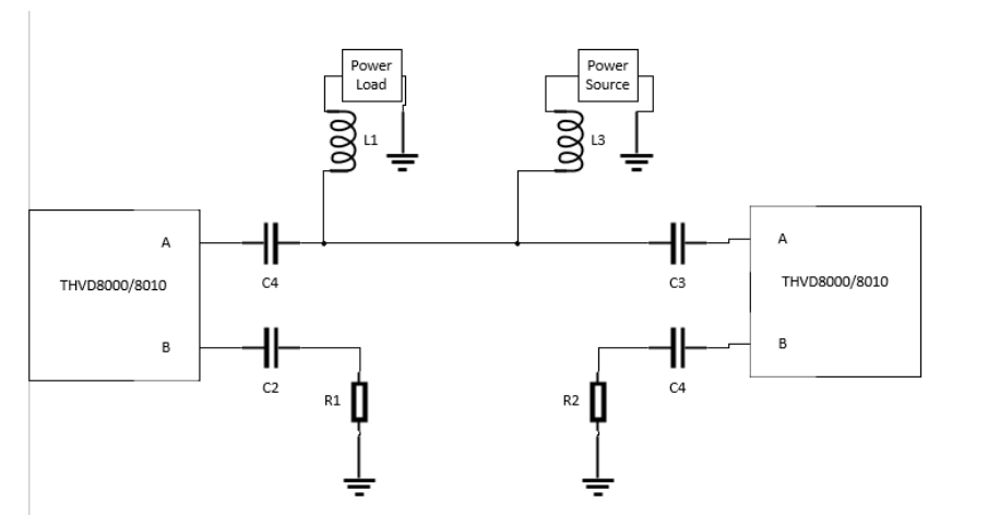
    1. The first check/change you can make to create a one wire communication (its a pseudo-differential implementation with the THVD8000) is to put a resistor after the capacitor connected between THVD8000 and the earth.

    Where the resistance value is equal to the resistance to ground as seen by the communication wire. 

    Where the resistance to ground as seen by the "A" port is given by:

    Assuming all inductors have the same value than the subscript on L is not that important and the Zin is equal for all THVD8000 (its minimum is 96k Ohms)  so having a resistor after the capacitor equal to the line impedance will maximize performance and avoid damaging the part due to high transient currents with direct capacitor to ground connections. 

    One note is that single wire only  requires inductors on the line used for communication so the final system could have half the total inductors. 

    If communication works after this change then it must be tested at the full distance with data-rate that you want to test.

    2. If communication still is failing at this point than most likely it is due to a limitation on the part with respect to system level needs. 

    This is possibly due to 2 things: distance and lower generated voltages from the driver.

    In 1 wire systems only about 1/2 of the total signal generated is sent towards the receiver due to the "B" port being connected to the common. So that is going to decrease max distance available to the system - we don't really have a number on the max distance in a one wire setup - we have a few documents that have brief mentions of the one wire set-up (the one in English can found here with the relevant section being 2.3: https://www.ti.com/lit/an/slla590/slla590.pdf?ts=1656009234599 - the other document that we have I don't think its published in English but the section is also small and has no different information that what I linked above). What I can say is that customers who use the single wire setup typically do so in systems with less than 10m of total bus length  - so with the distance you are trying to achieve it may be causing some issues.

    The next is a complication of data-rate vs. distance with the THVD8000.

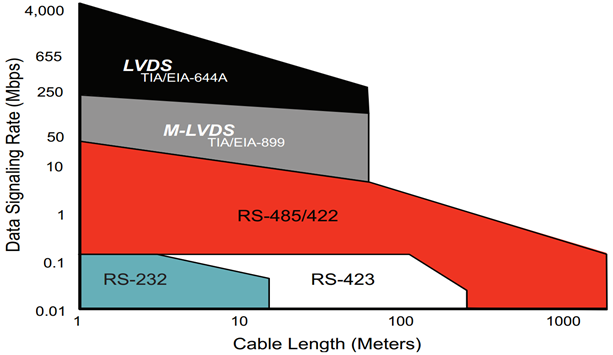
    For a typical RS-485 transceiver the data-rate vs. distance curve is similar to what is shown below in red:

    Where the fundamental frequency is 1/2 of the signaling rate --> the frequency  is what is of most concern as the THVD8000's data-rate is 1/10th of its output frequency so you need to look at this graph in terms of the modulation frequency (which the highest mod frequency on the THVD8000 is 5MHz - which is equal to 10Mbps on the graph above). That means in standard implementations you may limited to around 100m or so. This is assuming a differential setup - so with single ended wires you may be facing some more challenges. 

    So the solution in this case may require to either slow down the data-rate below the 500kbps (5MHz modulation frequency) with a single wire implementation or not do a direct connect. 

    If neither of these options are going to work for your system - the next solution is to take a look at the application note I linked above (here it is again: https://www.ti.com/lit/an/slla590/slla590.pdf?ts=1656009234599)  and follow the guidance there. Essentially the idea when you have higher voltage or low impedance lines the THVD8000 may not be enough on its own so using a line driver (we used the THS6222 in our design) to drive that line may be necessary to meet the goals of the application. Our design was tested at a 125KHz frequency but the design can be flexible with higher mod frequencies as the bandwidth of the THS6222 should be good for the application. The only change (we didn't include it in the application note as its already pretty long) for a DC system is that you don't need the transformer and the capacitor should be enough as solar panel inverters typically are our DC use case of the low impedance line driving. Also just as a note our test board was really just connecting the THVD8000 EVM with the THS6222EVM so you should be able to test the systems with EVMs if this is the route you wish to take. 

    So essentially you have a few options to go off of - ranging from simple fixes to more complicated arrangements - but I do think the THVD8000 (with possible additions of a line driver like the THS6222) can help to meet the systems goals that you are seeking - but I just want to mention that this is pushing the THVD8000 to its max so it may very well require the line driver if you cannot have a slower data rate.

    Please let me know if you have any other questions and I will  be happy to help  out!

    Best,

    Parker Dodson 


  • Hello Parker,

    Thank you for your last response.

    I did few tests in different configurations and it achieved to work.

    But we would like to increase the data rate and try to test the THS622.

    I saw in the documentation that the THS622 is unidirectional, and i need to send and receive data with each of our modules with a THVD8000.

    But I also noticed in this document this sentence: “In proper system design, THS6222 is inserted into the signal path in the drive mode and bypassed in the receive mode”.

    Do you have any information about how to implement the line driver THS6222 in a half-duplex system with THVD8000?

    Have a good day,

    Cordially.

    Hugo

  • Hi Hugo,

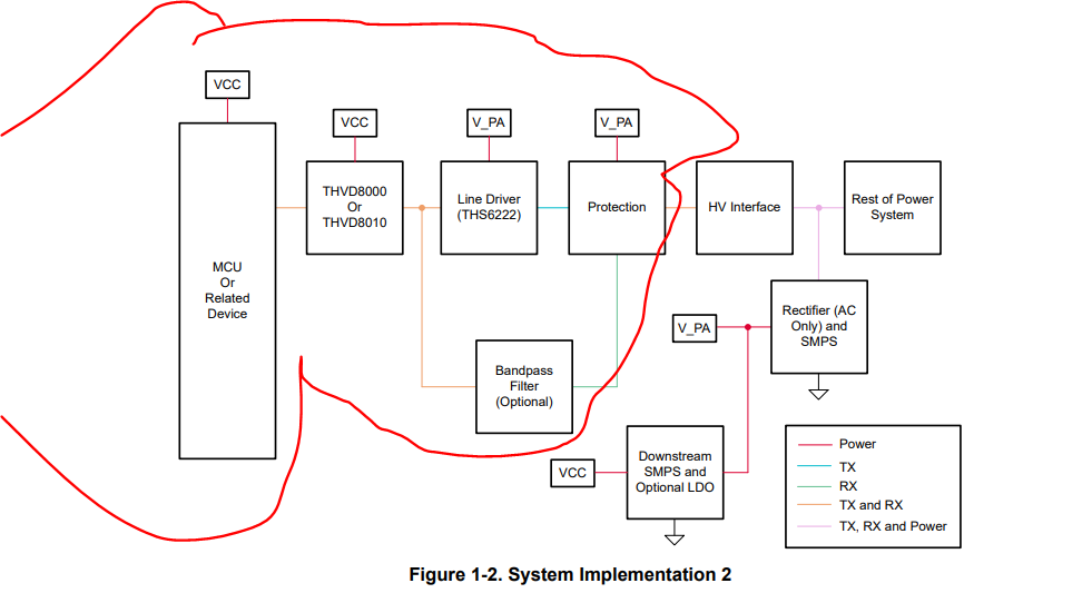
    From the original app note I linked:

    Essentially - while your system isn't the same as shown above - the right half is (circled in red) - essentially on the output of the THS6222 there is a band-pass filter that will reconnect to the inputs to make the system half duplex. (you don't need the filter necessarily - but it is in our designs)) It can be a challenge to implement though due to a not ideal layout setup - there is a full schematic shown on page14/15 of https://www.ti.com.cn/cn/lit/an/slla590/slla590.pdf?ts=1657206254191&ref_url=https%253A%252F%252Fwww.google.com%252F and essentially the bandpass filter would reconnect back to the first THVD8000 instead of going to a separate one - we show the separate version because its by far the easier one to implement.  This system could also be helped by a switch - to break the drive path when you are in RX mode etc... the switch could help prevent bad data. 

    Please let me know if you have any other questions!

    Best,

    Parker Dodson

  • Hi Parker,

    Thank you again for your answer.

    If I understand it well, i will have to do something like this:

    As the filter is not required in DC, I chose to not put it in the diagram.

    Do you think my diagram is correct?

    If not, what would you change?

    Have a good day,

    Cordially.

    Hugo

  • Hi Hugo,

    Yes that looks correct - the filter is optional so its okay to have it removed (especially in DC power applications) 

    If you have any other questions please let me know!

    Best,

    Parker Dodson