This thread has been locked.

If you have a related question, please click the "Ask a related question" button in the top right corner. The newly created question will be automatically linked to this question.

RS - 485 data pin control by msp430

Other Parts Discussed in Thread: MSP430F5438, SN65HVD11, SN65HVD12, MSP430G2553

Hi,

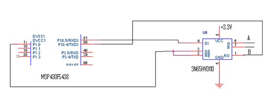
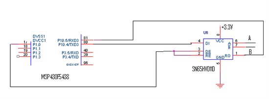
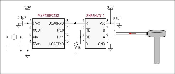
I am using Msp430f5438 and Sn65hvd11 for rs485 connectivity.

Now as we all know i will have to control data flow pins, so i have tied my one GPIO pin to both DE and RE of SN65hvd11d.

As one of suggestions from forums i used UCBUSY to check if all data has been sent or not after this i toggle the RS485 control pin.

Now my question is that it works fine in some cases when i use two ports of same controller and if on one side i have rs485 to 232 converter and at other side i have TTL to usb converter.

But if i use wireless connectivity at one side and rs485 to 232 converter at other side it doesn't work good.


So can anybody please guide how i can do this connectivity using control pin.Are there any other ways to do that in MSP430?


Regards.

  • Pallav,

    the fact that your RS485 connection works makes it more a control interface problem residing with the MSP430.

    But before I recommend  to contact the MSP430 or wireless connectivity forum, is there a chance that you could send us your schematic?

    Thank you,

    Thomas


  • Hi Thomas,

    Here is the controller and sn64hvd11 connection diagram.

    Please go through this and suggest me a solution.

    And if you have any sample codes or application note for this please guide me.


    Regards,

    Pallav.

  • as far as I can tell you got pin 80 and pin 81 mixed up.

    Regards,

    Thomas

  • Hi Thomas,

    Thanks for your reply. 

    Sorry but i sent you the wrong connection diagrams.Actually the diagram is as follows.

    I once again apologies for the mistake.


    Regards,

    Pallav.

  • Pallav,

    your schematic looks correct and the RS485 transceiver should work. I can't recommend anything else but contacting the MSP430 or wireless connectivity forum.

    Sorry to be of no further help.

    Thomas

  • Hi, add a pullup resistor to Rx wire to prevent false start on MSP. I hope on P10 there where no pullup to enable.

     Before to switch to tx mode wait some time to prevent bus fight, connect an oscilloscope to bus and observe transient how much time need to quiet, on fight case it disturb both bus and wireless communication.

     Regards

  • hi pallav...

    iam working with the same schematics...and got the same problem....iam using MSp430g2553(p1.1 and p1.2) and sn65hvd12..

    my p1.1----------------pin1(r) of sn65hvd12

    p1.2-------------------pin 4(d) of an65hvd12


    can you tell me how u solved this problem.....and also how u togelled(direction control pin) .....can you share the code for the same........


    Thank you

    Regards

    Rahul

  • hi rahul..

    i m thinking to use sn65hvd12 rs485 transciever interface with msp430g2553 with same schematic as you and pallav used.

    Actually in our application we want that controller shoul read data from fuel sensor that gives rs485 output.

    While msp 430 is not having rs485 port pins else it have uart pins.

    So is it possible to interface sn65hvd12  with msp430 so that msp430 could read fuel sensor rs485output signals through sn65hvd12.

    But if you are facing some problem then let us know, so that we can go for some other solution.


  • hi sheetal....

    fuel sensor giving RS485 output what does that means?...RS485 is an electrical standard.....

    MSP430 will not have RS485 pins.....it is having serial communication pins (UART)...which if u want to use in RS485 electrical standard,u have to use RS485 transceiver IC..

    Yes it is possible to use sn65hvd12 ic with your MSp430...u can connect the same as shown in schematics....the only thing is you have to control RE/DE(directional control pins) pins in Transceiver IC with the MSP430.....because at one time IC can act as either transmitter or receiver.....

    Regards

    Rahul

  • Because the fuel sensor is a transmitting device only, you would need to configure the HVD12 into constant receive mode. This is done by grounding the /RE and DE pins. I always connect enable pins via resistors to ground or Vcc to limit any noise currents that might be induced by noise transients low. I also grounded the data input D to avoid floating inputs.

    Regards, Thomas