This thread has been locked.

If you have a related question, please click the "Ask a related question" button in the top right corner. The newly created question will be automatically linked to this question.

DS90UB960-Q1: DS90UB960-Q1: Ds90ub960 receives data from ds90ub935, but 0x4d displays receive input does not meet PASS criteria

Part Number: DS90UB960-Q1

Dear Ti,

I use the ds90ub960 deserializer to receive the data transmitted by the camera.

The internal serializer of the camera is ds90ub935.

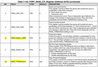
However, when I read the 0x4d register, its value is 0x39, indicating that the received input does not meet the pass criteria.

Can you help me see why?

The deserializer and serializer can communicate through I2C, and the camera can send data as soon as it is powered on.

The data format is raw16, and the lower 12 bits are valid.

Xinyu.

  • board.WriteI2C(dev_addr,0x4C,0x01)  
    
    board.WriteI2C(dev_addr,0x58,0x5E) 
    
    board.WriteI2C(dev_addr,0x72,0x00+port) 
    board.WriteI2C(dev_addr,0x5C, serializer_alias)              
    board.WriteI2C(dev_addr,0x6E,0xAA)
    board.WriteI2C(dev_addr,0x6F, 0x98)
    board.WriteI2C(dev_addr,0x7C, 0x00)
    board.WriteI2C(dev_addr,0x58, 0x5E)
    board.WriteI2C(dev_addr,0x6D,0x7c)             
    board.WriteI2C(dev_addr,0x7D,0x01)                            
    board.WriteI2C(dev_addr,0x18, 0x01)  
    board.WriteI2C(dev_addr,0x10,0x91)
    board.WriteI2C(dev_addr,0x19,0x15)
    board.WriteI2C(dev_addr,0x1A,0xB3)
    board.WriteI2C(dev_addr,0x1B, 0xC3)
    board.WriteI2C(dev_addr,0x1C, 0x4F)
    board.WriteI2C(dev_addr,0x32,0x01) 
    board.WriteI2C(dev_addr,0x33,0x03)   


    This is my initialization sequence

  • Hello Xinyu,

    When you power-up the system, does the processor or display show any flickering or loss of video data. I noticed that the LOCK_STS_CHG bit in register 0x4D is also set, so can you test to see if LOCK is stable, by reading register 0x4D multiple times, with a small delay between each read?

    If the LOCK_STS bit is always set to 1 and the LOCK_STS_CHG bit remains constant at 0 after multiple reads, then the LOCK is stable.

    In regards to the PASS status on the 960, the designer can set the conditions on which PASS is lost in register 0x7D. Your configuration script shows that register 0x7D = 0x01. This means that the PASS_PARITY_ERR bit is set to 0 and the PASS_THRESHOLD bit is set to 1.

    When PASS_PARITY_ERR is set to 0, the port PASS indication is deasserted for every parity error detected at the receiver port.

    Best,

    Justin Phan