This thread has been locked.

If you have a related question, please click the "Ask a related question" button in the top right corner. The newly created question will be automatically linked to this question.

DS90UB954-Q1: About Margin Analysis

Part Number: DS90UB954-Q1
Other Parts Discussed in Thread: USB2ANY, ALP

Hi, Team

Please elaborate on the following answer.

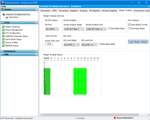
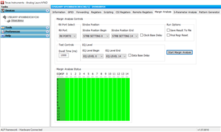
DS90UB954-Q1: Margin analysis measurement

It is stated that it is recommended to turn off the image sensor on the Serializer side.
However, the device with the Serializer is designed by another company, so it is not possible to turn off the image sensor.
Is it possible to perform a normal margin analysis even if the image sensor is on?

Best regards.

  • Hi Okano-san,

    Thank you for your inquiry. To clarify, is the camera module packaged into a housing and it is not possible to disconnect the serializer from the camera sensor? If this is the case, would it be possible to disable the output of the camera sensor by initiating a remote I2C command through the ser/des to the camera?

    Best,

    Thomas

  • Hi Thomas-san,

    Thank you for your answer.
    The camera module is housed in an enclosure and the serializer cannot be removed from the camera sensor.
    We are in a situation where we cannot disable the output of the camera sensor because there is no I2C command disclosed to disable the output of the camera sensor.

    Is it possible to do margin analysis without stopping the camera sensor?
    If not, I am planning to purchase and use the serializer EVM.

    Best regards.

  • Hi Okano-san,

    Thank you for providing these details. Let me discuss this with my colleagues to identify if we may be able to run the margin analysis program while there is CSI-2 data also being transferred across the link. I will get back to you with feedback by early next week at the latest.

    Best,

    Thomas

  • Okano-san,

    There is no need to disable the image sensor actually during MAP - the only thing you need to be aware of is that imager data passthrough will be disrupted during the test 

    Best Regards,

    Casey 

  • Hi Caesey,

    Let me give you some background on the question.
    We performed a margin analysis by connecting a USB2ANY to the deserializer while the device on the serializer side (serializer + camera sensor) was running.
    However, it was all green in EQ0-14 and SP0-14.

    In doubt, I searched E2E and found the answer attached to my first question.
    I would like to know if there is any flaw in the results of my margin analysis, as you said that I do not have to stop the camera sensor.

    Best Regards,

  • Hi Okano-san,

    As Casey confirmed, we should be okay to run the MAP tool while imager data is still running. Do you have the result from the MAP test which was completed?

    Best,

    Thomas

  • Hi ,
    Sorry for the late reply.

    I am connecting DS90UB933 and DS90UB954 with STP cable.
    The data format is YUV422 8bit.
    MAP was performed with USB2ANY connected to the 954, and everything was green at EQ levels 0-14 and strobe 0-14.
    The results did not change whether the image sensor was activated or deactivated.
    Is the margin analysis being performed correctly?
    Please let me know your view.

    Best,

  • Hi Okano-san,

    Do you have a picture of the MAP result?

    Best,

    Thomas

  • Hi Thomas,

    Sorry for the late reply.
    I will paste a picture of the result.

    The strobe position is 7 minimum and 10 maximum from SNLA301 in the application report.
    EQ level is set as default (min 3, max 14).


    Best,

  • Hi Okano-san,

    Thanks for following up. Could you confirm that the remote registers are accessible on the 933? It looks like the partner is listed as 953 here with no I2C address noted. You may have to go to the remote registers tab of the 954 and select port0 to have this setup correctly.

    Best,

    Thomas

  • Hi Thomas,

    Thank you for your response.
    I have selected port 0 in the remote register tab.

    I have done remote access to the image sensor connected to the serializer, but have never implemented remote access to the serializer.
    DS90UB954-Q1: About Pass Through Settings - Interface forum - Interface - TI E2E support forums

    What are the register settings to allow remote access?

    Best,

  • Hi Okano-san,

    You can enable remote access to the serializer by setting the SER_ALIAS_ID. After setting this register we can access the serializer through the specified alias.

    Best,

    Thomas

  • Hi Thomas,

    Thanks for the answer.
    But setting SER_ALIAS_ID did not work.

    (1)I set SER_ALIAS_ID to 0xB4.

    (2) When I selected the Remote Registers tab, I got the popup as shown below.

    (3) After pressing OK, "0xb4: DS90UB953" is displayed at the bottom of the tab.
    If you change the SER_ALIAS_ID to another value instead of 0xb4 and perform from (2), the value here will change.
    For example, if you set 0xb2, "0xb2: DS90UB953" will be displayed.
    But the I2C_DEVICE_ID value of 0x00 is 0x00.
    Since the serializer is DS90UB933, I don't think it is remoting well.
    Can you please tell me the cause?

    Best,

  • Hi Okano-san,

    Could you please check register 0x58 on the port of the 954 which the serializer is connected? I'd like to ensure that the proper back channel rate is selected for compatibility between the 954 and 933

    Best,

    Thomas

  • Hi Thomas,

    Thank you for your prompt reply.
    It is very helpful.

    The address 0x58 in 954 is 0x18.
    I believe the back channel is fine.

    The print screen does not select RX Port, but in fact, RX Port is selected and the register value is 0x18.

    Best,

  • Hi Okano-san,

    Let me check back on this case tomorrow. One question, it seems that we've strayed away from the main question on margin analysis result. Is this still the question which you're interested in?

    Best,

    Thomas

  • Hi Thomas,

    Thank you for your response.
    I am still having trouble with this issue because the task is not completed until the results of the margin analysis are available.

    The following is a summary of the situation.

    ---------------
    Problematic event
    In the margin analysis, the result is all green.

    Cause of the problem
    Remote access to the serializer is not enabled.
    However, even if the register settings are changed, remote access is not enabled.
    ---------------

    By the way, please tell me one thing.
    Is it OK to use the default register settings for the serializer?
    Is there any register in the serializer that sets remote access?

    Best,

  • Hi Okano-san,

    Cause of the problem
    Remote access to the serializer is not enabled.
    However, even if the register settings are changed, remote access is not enabled.

    What does this have to do with the MAP tool result? Are you saying there is no lock at all between the SER and DES?

    Depending on length of cable and utilization of available link bandwidth, an all green MAP tool is sometimes valid/expected. 

    There is no need to disable the image sensor actually during MAP - the only thing you need to be aware of is that imager data passthrough will be disrupted during the test 

    Can you clarify what the exact issue is here? 

    Regards, 

    Logan

  • Hi Logan,

    >What does this have to do with the MAP tool result?
    My first question is as follows.
    "In the margin analysis, the result is all green and I believe it is an anomaly, do you know why?"

    Thomas's Answer.
    I think the reason is that remote access to the serializer is not enabled.

    So I interpreted that the margin analysis is all green because remote access is not enabled.

    >Are you saying there is no lock at all between the SER and DES?
    The serializer and deserializer are locked.
    (The display data from the image sensor connected to the serializer can be displayed on the TFT on the deserializer side.)

    >Depending on the length of cable and utilization of available link bandwidth, an all green MAP tool is sometimes valid/expected.
    This is the first time I've heard of this.
    Are you saying that depending on the length of the cable and the use of available link bandwidth, it can be all green?
    So all green is normal, not abnormal?

    Best Regards,

  • Hi Okano-san, 

    Can you enable all the EQ and strobe values to get the full table instead of only the sub-set? 

    Regards, 

    Logan

  • Hi Logan,

    The requested image is attached.
    Please check it.

    Best regards,

  • Hi Masanori, 

    Thanks for the info. I see you are doing 2560x720 data from camera, is this correct? What refresh rate is being used? Low PCLK/line rates will increase likelihood of all green result.

    Regards, 

    Logan

  • Hi Logan,

    Refresh rate will be 30 fps.
    Would 30fps result in all green?

    If I change it to 60fps, will it not be all green?

    Regards,

  • Hi, 

    What image resolution are you sending?

    Looks like it is only linking at 48MHz, which is relatively low bandwidth use of the available link. You might try increasing the FPS to see if that impacts link margin. Under this condition, can you retake a snapshot of the information tab? 

    Also, what cable length is being used? 

    Regards, 

    Logan

  • Hi,

    I am sending an image resolution of 1280*720.
    Since it is YUV, I believe the ALP shows 1280*2=2560.

    The pixel clock is 48MHz*2=96MHz.
    I said 30fps, but this is a target value, and the current state is 52fps.
    (96MHz/(2560*720) = 52.08Hz)

    Cable length is 2m.

    If I am wrong in my thinking, please correct me.

    Regards,

  • Hi Okano-san,

    Thanks for the details. I will discuss this with Logan tomorrow.

    Best,

    Thomas

  • Hi Okano-san,

    I tried to replicate this on a set of ser/des EVMs today, and found also found that the screen was all green. One question which I have, have you been using the RX0 or RX1 port on the 954 evm? As detailed in the 954 EVM user guide the RX1 port  is setup for usage with the 933. I also saw that the cable was noted as twisted pair not coax, could you confirm?

    The result of all green in the MAP tool is not entirely unexpected as the forward channel from the 933 is comparatively easier to recover at the deserializer side compared to the higher speed forward channel from the 953.

    Best,

    Thomas

  • Hi,

    Thank you so much for reproducing this on the ser/des EVM set.

    I use both ser/des boards that I designed myself.
    I don't use EVM because I don't have it.
    I used STP instead of coax because I designed it with STP.

    So in summary, you are saying that the result of the margin analysis being all green is a normal result, not an anomaly.
    If there is no problem, we will close it.

    Best Regards,

  • Hi Okano-san,

    Thanks for your clarification. We should be good to close then as this can be a valid result at the lower speeds used in your application.

    Best,

    Thomas