This thread has been locked.

If you have a related question, please click the "Ask a related question" button in the top right corner. The newly created question will be automatically linked to this question.

DS90UB947-Q1: 947+948 force secondary link mode (single link)

Part Number: DS90UB947-Q1
Other Parts Discussed in Thread: ALP

hi Team, 

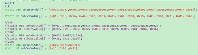
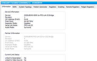
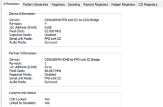
Customer would like to make 947+948 work in secondary link only mode (ROUT1--RIN1), keep the primary link disconnected, could you help confirm how to configuration?

Looking through the datasheet, it seems default setting should work

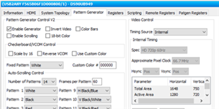
  • 947: 0x5B[0] works in Auto-Detect FPD-Link III mode
  • 948: 0x34[3:4] Auto-detect based on received data

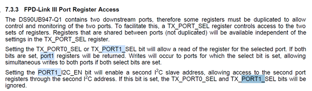
May you also check the impact to I2C/GPIO pass-through function with secondary link only?

Regards,

Dongbao

  • Here are the script for 947 and 948, could you help modify and make it works in secondary link only mode? Thanks.

  • Hi Dongbao,

    Thank you for your question. As long as you leave the 947 and 948 in auto-detect mode, via the registers you identified, this configuration will work without any other changes needed.

    Regards,

    Darrah

  • Hi Darrah,

    Thanks for your feedback.

    1. Could you confirm whether i2c and gpio passthrough function is impacted by the secondary link operation since customer confirm the system works on primary link only mode but not secondary link doesn't work?

    2. If Q1 is not impacted, what are the purpose of TX_PORT1_SEL and PORT1_I2C_EN bit? Can you share the application scenario? Since 947 could only support one downstream device 92x/94x, i don't see the needs of independent port0/1 registers.

    regards,

    Dongbao

  • The DS90UB947-Q1 automatically detects the capabilities of downstream links and can resolve whether a single device, dual-capable device, or multiple single link devices are connected. The proper operating mode and function is then automatically selected based on the detected configuration. For example, connecting two devices (dual link) will result in replicate mode and connecting a device on only the secondary link will result in video only being sent on the second link. However, there must be no connection on the primary link for auto-detect to be successful.

    The independent port registers allows access to the registers of a specific port since many are duplicated (one for each respective port). Setting one or both of these ports allows for direct control over the respective registers.

    The PORT1_I2C_EN bit enables a second I2C slave address specifically for the second port. Setting this register (0x1E[2]) means you will use the base I2C address + 1.

    If the customer is having issues accessing I2C with port 1 then setting 0x1E[1] is recommended. 

    Regards,

    Darrah

  • Hello Darrah:

    Thanks a lot for your information. I will show you the progress of issue solving.

    1. only PORT 1 is hardware linked, PORT 0 is disconnected. in this situation, we set 947 in auto-detect mode, and then set 948 in auto-detect mode(auto-detect mode is default settting), there is no vedio link worked. I guess in this senario, Ser 947 and Des 948 is waiting for each other, there is no device to step first, that is the reason no vedio link worked.

    2. only PORT 1 is hardware linked, PORT 0 is disconnected. in this situation, we set 947 in auto-detect mode, and then set 948 in Forced input on PORT1 mode(this setting can not be done by 947 because IIC link is not work, we set 948 by additional MCU in 948 side), in this senaria, Vedio link is worked, and the pic and be showed in display. but the problem is IIC link is not work, even if PORT_SEL1 bit are set in both 947 and 948 side. 

    so in our application: only traminit on PORT1, we do not need to enable second IIC by set PORT1_I2C_EN bit as 1, am I right? can you explain the function of 2nd I2C?

    and for our applicaiton requirement, a MCU is mandatory in 948 side to enable FORCED input on PORT1 mode. do you agree?

    waiting for your feedback, have a nice day!

  • Hello Darrah,

    We have experimented with 947 and 940 EVM boards:

    1. Only connecting to PORT0 (949: DOUT0+, DOUT0-; 940: RIN0+, RIN0- ), use the default configuration and you can communicate directly.

    Read Remote Registers successfully

    .

    2.Only connecting to PORT1 (949: DOUT1+, DOUT-1; 940: RIN1+, RIN1- ), using the default configuration, the communication cannot be successful. As shown in the figure, the Remote Registers cannot be read.

    Change the value of  the register 0x34[] :value 0x01 to 0x1B, 940 can read Partner Information of 949, but the Partner Information is grey and the Remote Registers cannot be read.

    The corresponding 949 terminal cannot read the information of 940 at all.

    Change the register 0x1E[] in 949: Value 0x01 to 0x02, and display the connection to the Deserializer, but the display is 926, and the Remote Registers still cannot be read.

    3. Keep the configuration and connection method in 2, and Check Enable Generator, and change Timing Source to Internal.

    On the 940 side, you can see the 949 information, and it shows that the connection is Yes, and the Remote Registers of the 949 can be read.

    But on the 949 side, you can see that the Partner Information can read the information of 940, but it is gray, and the Remote Registers cannot be read.

    To sum up the experiments:

    1. When using Port0, the default configuration can be used.
    2. When using Port1, the mode cannot be used, and the auto selection channel set in the middle will not work, so it must be manually changed to the corresponding port1 register.
    3. After configuring the corresponding registers, the 940 can read the information of the 949, and can read the Remote Registers. But conversely, 949 can only read the information of 940, but cannot read Remote Registers.

    This phenomenon is consistent with the customer's board.

    May I ask if our board can complete the communication using only Port1? If so, what other configuration needs to be done?

    Regards,

    Xiaoxiang

  • Hi Dechao and Xiaoxiang,

    Thank you for the detailed updates. 

    The second I2C address (enabled by setting PORT1_I2C_EN) enables a I2C address specifically for Port1. For example, when only Port1_SEL is set register access for Port1 will be from the primary I2C address. When the second I2C address is enabled access to Port1 registers will be from the address DeviceID+1. This is essentially giving each port a specific address. For your application the primary address should be enough since you are only using Port1, but it may be worth testing if the remote registers could be read with the secondary address.

    The 948 does have a forced input mode via the DUAL_RX_CTL register, which could be an option other than the MCU.

    Just to confirm, have you enabled I2C pass-through or set any slave alias? When you attempt to read the remote registers are they all set to zero or are you unable to see anything? Could you also check the values of registers 0x5A and 0x06 on the serializer side? It is odd that there is no link to the deserializer. 


    Regards,

    Darrah

  • hi Darrah,

    Can you set up the bench test in the lab? It's easy to replicate the issue that customer and field are facing with.

    For ALP and EVM, the i2c pass through is enabled automatically when you try to read out all the remote registers; As you see from the screen shoot, 949 could detect the deser i2c address but not able to identify 940. 

    The method you mentioned to set PORT1_I2C_EN, we also tried and change the i2c address from 0x58 to 0x5B (0x06 register address), it doesn't work.

    Based on current findings, i think the statement in datasheet is not accurate. Pls check with designer and retest in your lab.

    Regards,

    Dongbao

  • Hi Dongbao,

    I will look into this on the bench and update you next Wednesday (7/27). In the meantime could you try manual I2C reads and writes through the scripting tab? Can you confirm that the slave alias has been set up?

    Regards,

    Darrah

  • Hi Dongbao,

    It is taking a little longer to replicate the issue on the bench. I will update you on Friday.

    Regards,

    Darrah

  • Hi Dongbao,

    Thank you for your patience with this issue. Replicating and finding a solution will take some more time. I will update you again by Tuesday.

  • We've managed to replicate the issue and found a sequence that allows for manual script reads and writes to remote registers to both the forward and back channel. We will continue looking for a more straightforward method that allows access through the remote registers tab. I will update you by the end of the week.

  • Hello Darrah:

    I am the End user for this case. Firstly thanks a lot for your support.

    and your check result will impact my project change, I will waiting for your good news in this week.

    Thanks.

  • Hey Li,

    We have figured out the issue and created a working script. We are working with the 949 and the 948. Please follow these steps to replicate the solution on your side:

    1. Only connect to PORT1 (949: DOUT1+, DOUT-1; 948: RIN1+, RIN1- )

    2. On the 948 side: Select register 0x34 -> 0001 1000 (0x18)


    3. On the 949 side: Set Pattern Generator to enable generator and toggle timing source to Internal

      1. The 948 should be able to recognize and talk to the 949 now

    4. On the 949 Side: 
      1. Create a python file with the following code to change the following registers. You may need to change the registers/device address for the device that you are using.
        serAddr = 0x18
        desAddr = 0x58
        
        board.WriteI2C(serAddr,0x1E,0x04) # Enable secondary I2C address for port 1
        board.WriteI2C(serAddr+2,0x03,0xDA) # Enable I2C passthrough on port 1
        print hex(board.ReadI2C(desAddr,0x00,1)) # Read DES address
      2. Run the code on the 949. 949 should be able to talk to the 948 without any issues now and vice versa.
      3. The ALP software will not recognize the 948. But the forward channel is in operation now

    Please let me know if you are able to replicate the solution on your end. 

    Respectfully,

    William Yi