This thread has been locked.

If you have a related question, please click the "Ask a related question" button in the top right corner. The newly created question will be automatically linked to this question.

SN65LVDT41: Driving 21 LED display panels using LVDS

Part Number: SN65LVDT41
Other Parts Discussed in Thread: SN65MLVD040, SN65LVDM31

Hello

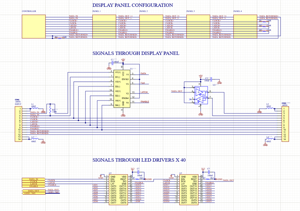
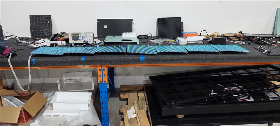
I am trying to send 215,040 bits of data across 21 LED display panels which add up to a length of 7.3m.
We are currently using RS485 drivers to send the data across all the LED panels.
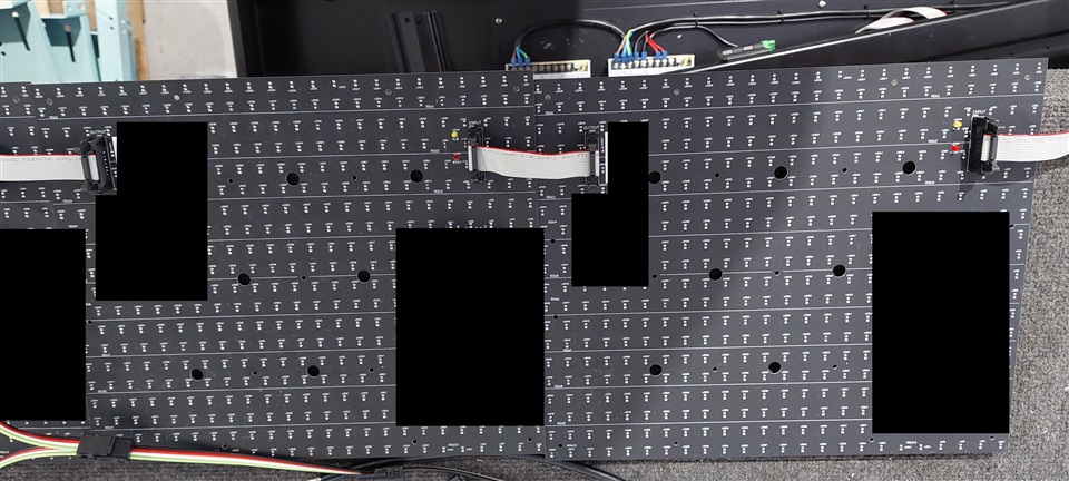
The clock, latch and enable signals are configured as multidrop whilst the data is sent as point to point as it must go through 40 LED drivers on each panel.
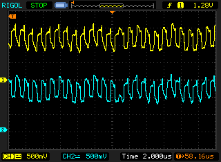
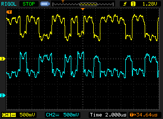
The problem is we can't get the speed needed to update the signs quick enough using RS485 so we are testing out LVDS technology.
I have just tested the SN65LVDT41 as a quad driver and SN65LVDS32PW as a quad receiver, then the data output will get sent out by SN65LVDM176DR driver.
Unfortunately I was only able to drive 5 panels successfully which is roughly 1.75m and I was expecting to be able to drive about 10m.
Can anyone explain to me where I might be going wrong?
Would it be possible to go point to point between each panel so all the signals are going in and out of each panel that are connected over 21 panels then the data returned back through all the panels and back to the controller?
I have also seen that M-LVDS may be able to drive longer distances which is what I am going to test next as converting the PCB to point to point will call for a PCB change.
The signal traces also go through about 40cm of PCB so wondering if that is also causing issues and if the connectors on the PCB should be moved closer together to minimize the length of the PCB traces and increase the cable length.
We are also only using ribbon cable into a 14 pin IDC header so wondering if that could also be causing some issues.
Any information and guidance will be greatly appreciated.


Thanks


Craig

  • Hi Craig,

    There could be multiple reasons for the data to not traverse all the panels. Can you share any waveforms to help understand what is going on? Cable length driven is mainly effected by the allowable jitter in the data. You can refer to this document for some background info: https://www.ti.com/lit/an/slaa844/slaa844.pdf 

    Ribbon cable would perform as well as shielded twisted pair cable like CAT5e cables. Were the PCB traces routed following principals in this document: https://www.ti.com/lit/an/snla302/snla302.pdf?   

  • Hi Malik

    Not sure if this is the how to share images but I have taken photos of the data, clock and data returned on the 1st 2nd and 3rd panels.

    The data looks very noisey by the time it gets to the 7th panel, I tried returning the data via a cable instead of going through all the panels and it looked a lot cleaner but still got errors.

    Thinking the state of the clock signal by the time it gets past the 5th panel is causing the LED drivers to output some errors.

    I think ideally the cables need to be longer between each panel and have the connectors close together to limit the length of signal traces running through the PCB.

    Also not sure of the driving capabilities of the SN65LVDT41 as it mentions in the data sheet is best used for point to point, I will try an M-LVDS driver to see if that improves anything.

    Any further information on how I can improve the signal integrity will be highly appreciated.

    Thanks


    Craig

  • Hi Craig,

    Let me review this and get back to you. 

  • Hi Craig,

    I can't view the images you shared, can you attached them directly to this thread? Can you share a block diagram of your desired configuration? Also any s-parameters of the cables used would be useful to give some recommendations.. 

  • Hi Malik

    Sorry just worked out how to attach photos from PC. Here is a block diagram of the setup I have.

    The Data going into panel 1.

    Clock going into panel 1.

    Data going into panel 7.

    Clock going into panel 7.

    Data out from panel 7 (Data being returned to controller).

    Data return after returning back to controller.

    Bench Setup.

    Back of LED panel

    We are just using ribbon cable to transfer the data between boards.

    Thanks

    Craig

  • Hi Craig,

    It seems there is some crosstalk from he CLK signal to Data and some low frequency noise on the clock signal. Do you have external resistors on each Data LVDS pair? Do you see similar ripples on single-ended signals? 

  • Hi Malik

    Ye, thought that's what it might be. No external resistors just some common mode filters. The single-ended signals actually looks fine, I think the crosstalk was coming from the graphics clock so I have disabled that and the signal is a lot cleaner but still getting errors on the 6th panel whenever that is connected no matter what speed I drive it at and up to the 5th panel works fine up to 8MHz. If I remove the common mode filter there is a 200KHz noise on the data signals which I assume is coming from the switching regulator. So with the graphic clock disabled and still seeing faulty data it makes me wonder if the distance/amount of receivers is too much for the SN65LVDT41.

    Clock single end yellow, differential blue when graphics clock is enabled.

    Clock single end yellow, differential blue when graphics clock is disabled.

    Clock single end yellow, differential blue when graphics clock is disabled and common mode filter removed.

  • I agree that the amount of receivers may be too much for SN65LVDT41. This device is designed for point to point applications (1 driver to 1 receiver). Additional receivers come with additional parasitic which most likely are eating into your jitter budget. Do you have a waveform of a corrupted packet? 

    Here you have multiple of these devices sitting on the same bus, right? I believe you would get better performance  will want to use MLVDS devices for this kind of application such as SN65MLVD040. 

    https://www.ti.com/interface/lvds-m-lvds-pecl/products.html#p1389=M-LVDS&sort=p993;desc 

  • Hi Malik,

    Yes I did read that on the datasheet and did also try SN65LVDM31 as a MLVDS driver but the display panels didn't work at all. This may have been because I still had LVDS receivers, assuming they are not compatible with each other.

    As I am using an existing design that used RS485, I was trying to find IC's that replicate the pin out already used so I was able to replace MAX3042BCSE+ with SN65LVDM31 but could not find any MLVDS receivers pin compatible with MAX3093EEUE as they all seem to be 48 pin QFN packages which seems odd to me why you would need that many pins for such a simple IC.

    Yes all 21 panels are on the same bus, looks like I might have to change the design to test it out but it could be an expensive test as would have to get all 21 panels made.

    It is strange though as the data being returned looks ok, previously it was being returned through the panels which looked horrible.

    Then I went from the end panel through a cable back to the controller and it is a lot cleaner but still seeing corrupted data.

    I will try and get some good images of the corrupted data.

    Thanks for helping me with this.

    Craig

  • Hi Craig,

    The interfaces are different, M-LVDS does not require termination at every receiver like you have now and use 50 ohm differential opposed to 100 ohm for regular LVDS. M-LVDS should be able to support you 21 boards.  I suspect that phase alignment is lost between the data and clock after ~6 panels which also contribute to corrupted packets. 

    SN65LVDM050 might be a closer fit here for you to try out.