This thread has been locked.

If you have a related question, please click the "Ask a related question" button in the top right corner. The newly created question will be automatically linked to this question.

TCAN1145-Q1: connector PIN position

Part Number: TCAN1145-Q1

Dear team,

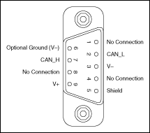
Do we have any requirements for the position of the CAN bus on the PINs of the controller connector? Does it require PINs to be adjacent?

Thanks & Best Regards,

Sherry

  • Hi Sherry,

    I'm a little confused by the wording controller connector. Can you elaborate on what connector you are referring to? Typically when you connect a CAN transceiver to a CAN controller you are connecting the TX and RX pins to the TX and RX pins of the controller.

    If you are just talking about connecting the CANH and CANL pins to a connector that will go to an external CAN bus then we don't have many requirements. There is a standard setup for a DB9 connector:

    This is the setup that we use on our EVMs and on the BOOSTXL-CAN booster pack. What stays consistent across all DB9 connectors is that CANH is pin 7 and CANL is pin 2.

    However, if you do not care about a standard setup then you can route pins however you like. They don't have to be directly adjacent to each other. However, what will help with performance is making sure that the two signal are differentially routed. That means that they have the same trace length. In practice this usually means that the two signals are adjacent to each other since that makes it easier for the traces to be the same length. It also helps to keep the signals close to each other since that will allow noise to couple onto the CANH and CANL pins equally which will help when trying to create a differential signal.

    In practice I think it is optimal to have the two pins adjacent to each other on a connector but it is not required.

    Best,

    Chris