Part Number: DS90UH947-Q1
Other Parts Discussed in Thread: ALP
Hi Team,
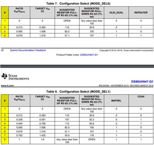
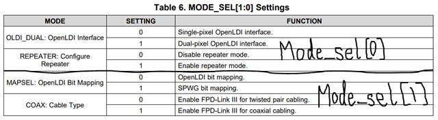
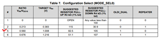
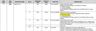
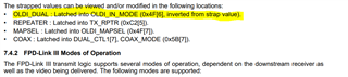
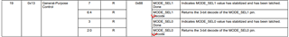
May you let me the content of below bit? I have no idea how to map to mode_sel0 table.
In addition, if we are working on dual pixel mode. Does it mean that we need let OLDI_DUAL = '1' ?
Roy