This thread has been locked.

If you have a related question, please click the "Ask a related question" button in the top right corner. The newly created question will be automatically linked to this question.

DS90UB960-Q1: Match DS90UB935-q1,Judge whether the frame data is correctly received

Part Number: DS90UB960-Q1

Dear TI,

The deserializer is ti960, and the serializer of the camera module is ti935.

Now the serializer and deserializer can communicate through I2C.

I want to ask the deserializer side or the serializer side, which registers can be used to confirm that the frame data has been transferred from the serializer to the deserializer.

Wish you a happy life.

Xinyu.

  • Hello Xinyu,

    Once the 935 and 960 are successfully LOCKed onto each other, you can check the LINE_COUNT and LINE_LEN registers in the 960 to detect the video data being received by the 960.

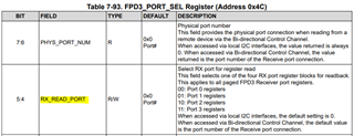
    First, select one RX Port to read from in register 0x4C.

    Next, read registers 0x73-0x74 in the 960 to get the 16-bit value for the number of video lines that the 960 received in the latest video frame that was sent.

    Then, read registers 0x75-0x76 in the 960 to get the 16-bit value for the number of bytes that the 960 has detected in each video line it received. Multiply that number by 8 (bits per byte) and then divide by the number of (Bits-Per-Pixel) for the data type of the video sent, in order to calculate the detected number of pixels that were received in each video line received by the 960 at the selected RX Port.

    I also recommend to monitor registers 0x4D and 0x4E for detecting possible errors that could occur at the receiver on the 960.

    Best,

    Justin Phan

  • Hi Phan,

    Thank you very much for your reply, it helped me a lot.

    Now these registers are all 0x00, does it mean that the camera module has no data transmission.
    One more question to ask: The 935's transfer rate is 3Gbps, while the 960's transfer rate is 4.16Gbps. Whether the different rates of the two chips will also affect the transmission of data, resulting in the possibility that the deserializer cannot receive data.
    Do the 935 and 960 have registers to configure the transfer rate of FPD-Link?
    Hope to hear from you and wish you a happy life.
    Xinyu

  • Hello Xinyu,

    First, can you double-check and make sure that the RX_READ_PORT register is configured for the specific RX Port that you are monitoring?

    For example, if your serializer is connected to RX Port 0 on the 960, then register 0x4C[5:4] should be equal to 00.

    After that, can you read register 0x4D multiple times and make sure you have a stable LOCK on the selected RX Port?

    The LOCK_STS bit should be a constant 1 and the LOCK_STS_CHG bit should be 0 after multiple reads, to indicate stable LOCK.

    If you have selected an RX Port to read from and have a stable LOCK at the selected RX Port, then the counter registers will be able to detect if video data is being received by the 960 at the selected RX Port. If you are reading 0x00 in all of the registers, then video is not being sent to the deserializer.

    The 935 actually can drive the Forward Channel (SER->DES) line rate at up to 4.16Gbps. The "3Gbps"  term used in the 935 datasheet is used to differentiate it from the 953 and show that it is a lower-cost option that will support less video throughput. The 953 can drive the Forward Channel at up to 4.16Gbps, of which consists of 3.328Gbps of video throughput. The 935 can drive the Forward Channel at up to 4.16Gbps, but only transfer 2.528Gbps of video throughput in that Forward Channel transmission.

    Video Throughput = HActive x VActive x FPS x Bits-Per-Pixel x Overhead (Assume 25% if unknown)

    The 935 and the 960 can LOCK and transfer video data if both devices have matching MODE settings. No additional configurations are required.

    Best,

    Justin Phan

  • Dear TI,

    Sorry for the late reply, thank you very much for your answer. It helps me a lot.

    Thank you,

    xinyu