This thread has been locked.

If you have a related question, please click the "Ask a related question" button in the top right corner. The newly created question will be automatically linked to this question.

DS90UB933-Q1: I2C back channel- Interleave register reading command issue

Part Number: DS90UB933-Q1

A. We are currently working on the following hardware configuration:

-ECU connect to de-serializer 934

-Image sensor (0x10) connected to 933(0x58) on the other  side

B. Problem

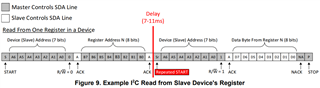
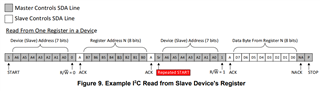
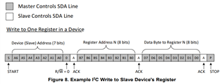
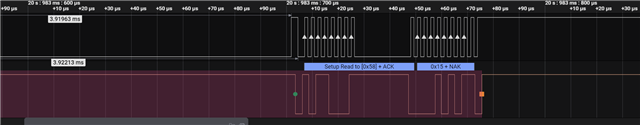
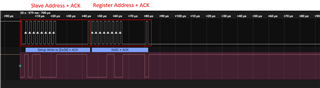
We observe that a single byte read from serializer is redding an undefined value if the 2 parts I2C read transaction ( WR to set register address and RD to get back register value) are separated by register write commands( to the sensor).

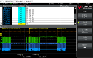
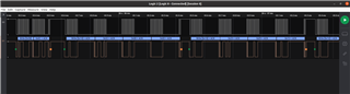
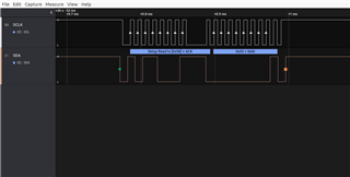
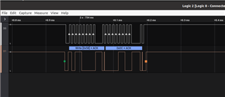
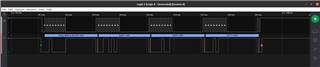
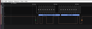
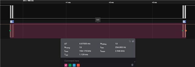
Please refer the logic analyser capture shown below. Read transaction with serializer (58W + 58R) is split by the high priority sensor (10W) transactions. Expected value is 0x11 (returned during uninterrupted/atomic read) but 0xF8 is read which seems to be a random value unrelated to the register address previously requested.


So questions are:

-Is interleaved register read command to the serializer a legal transaction?

-What could be the reason for the problem

-Is there any configuration to the back channel we should look at?
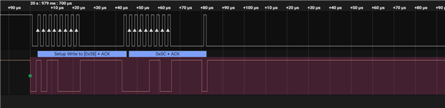
  • Hello Tri,

    On our FPD-Link devices, we do support remote I2C transactions from a Master on the Des to a Slave on the SER. In your setup, it seems you are trying to initiate two separate I2C transactions as part of a single I2C read of your Image Sensor (58W + 58R). But if a high priority sensor I2C transaction occurs on the I2C bus on the 933, which comes between the 58W and 58R command, then you are reading an invalid value.

    Is my understanding correct?

    What device is outputting the I2C transaction, which is marked as 10W?

    For reference, below are App Notes that describe I2C transactions over our FPD-Link devices:

    https://www.ti.com/lit/an/snla222/snla222.pdf 

    https://www.ti.com/lit/an/snla131a/snla131a.pdf

    Best,

    Justin Phan

  • Hi Justin,

    Yes, your understanding is correct. Our I2C bus topology is as simple as below. It is pretty standard as the ECU is the I2C master, it communicate with I2C device over the de-serializer 934 and on the other side of the FPD link is the serializer 933 and image sensor

    ECU ( I2C Master) <---I2C--> DE-SERIALIZER 934 <-----FPD Link----> SERIALIZER-933(ID=0x58) <--I2C--> Image sensor(ID = 0x10)

    An register read to the serializer is combination of a WRITE to provide the register address and a READ to get the register value back from the serializer. And when there is a high priority WRITE ( from the ECU to the image sensor ( with ID 0x10) the register value we read back from the serializer has invalid value.

    Thanks

    Tri

  • Hello Tri,

    If the ECU Master wants to send an I2C command to the Image Sensor, then the 934 DES will receive it on the local I2C bus, send it to the connected 933 over the cable link, and then the 933 will re-create the pulses on its local I2C bus. The 933 will also transmit the ACK bit back to the 934 I2C bus, to complete the I2C transaction.

    Below is another reference App Note about the I2C bus:

    https://www.ti.com/lit/an/slva704/slva704.pdf

    Here is an image from the App Note that discusses the sequence of pulses sent for an I2C read command that follows standard I2C protocol:

    Are you saying that if your ECU is in the middle of sending the I2C bits for a Read Command (Slave Address + Register Address + Slave Address + Data Byte), your ECU may interrupt and instead start sending a higher priority I2C Write Command instead?

    For example, say your ECU is in the middle of the I2C Read Command (Slave Address + Register Address), but then the ECU suddenly decides to do a higher priority I2C Write Command (Slave address + Register Address + Data Byte), before continuing to send the last 2 bytes in the previous I2C Read Command (Slave Address + Data Byte)?

    The end result is that the result of the I2C Read is some invalid value?

    Do you know if the write command was completed?

    Best,

    Justin Phan

  • Hi Justin,

    >>Are you saying that if your ECU is in the middle of sending the I2C bits for a Read Command (Slave Address + Register Address + Slave Address + >>Data Byte), your ECU may interrupt and instead start sending a higher priority I2C Write Command instead?

    Yes, we prioritize I2C WRITE to the sensor. When the ECU is in the middle of a I2C read on the serializer's register ( Register address over a WRITE has been done) but the there request on sensor setting we prioritize I2C WRITE to the sensor first and will resume I2C READ once all the settings to the sensor is done.

    >>The end result is that the result of the I2C Read is some invalid value?

    Yes, when there is interruption in between the Serializer's register read, the value of the register read back is no valid ( For example we expected 0x11 but the return value is random ( for example 0xF8 as we captured above)

    We do probe the bus, all the transactions ( WRITE to the serializer, WRITE to the sensor and READ from the serializer) look pretty normal with ACK/NACK and START and STOP bit as stated in your App Note documents ( as captured below) . The sensor's registers were written successfully too.

  • Hello Tri,

    You mentioned that the I2C bus was probed on the 933 serializer board and that no bits were missing for the READ and WRITE commands that were sent. Did you also probe the I2C bus on the 934 deserializer board, to make sure nothing is missing as well? For example, make sure the ACK bits are properly transmitted to the 934 I2C bus and also confirm the value of each byte sent on both buses.

    If possible, could you provide comparison pictures and highlight any differences?

    I have not encountered this type of issue before, so I am reaching out to other members of my team to discuss. Any additional information, images, or highlighted information would be beneficial.

    Best,

    Justin Phan

  • Hi Justin

    Thanks a lot for your support.

    Just to share some more capture of the bus in the failure case ( all these capture are on the I2C bus between the ECU and the 934)

    1. Register address WRITE to the serializer (0x058) and interleaving WRITE to the sensor

    0x58 Address WRITE and the WRITE to sensor

     2. READ from the serializer (0x58) which return invalid value

    All the transactions look pretty normal and follow the standard ( as stated with the application note that you have shared)

    Thank you,

    Kind regards,

    Tri

  • Hi Tri,

    Would you be able to get a close-up capture of the full I2C Read and Write sequence in the same picture, where the I2C Write bytes are easily identifiable and are splitting the I2C Read command?

    Similar to what you previously posted, but with both the I2C Read and Write bytes on the same picture for comparison.

    Best,

    Justin Phan

  • Dear Justin

    The 2 pictures above are 2 parts of the failure case. ( To make all the transitions readable we zoomed in and captured into 2 photos)

    In 1. you could see the 0x58W at the beginning, that is first part of the serializer read ( Set register address for reading). And then this is interrupted by multiple WRITE to the sensor

    And 2. shows the serializer's register reading is resumed with 0x58W after all the WRITE to the sensor are done. The invalid value we got back in this capured it 0x00 ( we expected 0x11). The invalid value is quite random

    Thanks,

    Kind regards,

    Tri

  • Dear Justin,

    I'd like to share some more photos of the failure transactions.

    1. The whole failure case, start with WRITE to the serializer, interrupting WRITE to the sensor and a READ from the serializer

    2. Zoomed in WRITE to the serializer

    3. Zoomed in  Sensor WRITE

    4. Zoomed in Serializer READ

    Please let us know if you need more captured data.

    Thanks,

    Tri

  • Hello Tri,

    Thank you for the clarification. I will post again once I get a response from some internal design engineers in our team, but feel free to request an update on the situation.

    Best,

    Justin Phan

  • Hello Tri,

    I was able to get a response. This type of I2C interleave transaction is not supported across the FPD-Link channel. While this is allowed in normal I2C protocol on a local bus, when you send I2C commands across the FPD-Link channel, the I2C commands must be complete and uninterrupted. You cannot interleave different I2C commands between the bytes in an existing I2C command and expect the existing I2C command to complete properly.

    Our FPD-Link devices re-create the I2C transactions from the local I2C bus and send them to the I2C bus on the connected device, but the STOP command bit in the middle I2C Write transactions will trigger the Back Channel logic to end the I2C pass through transaction, effectively cutting off the original I2C read command.

    Best,

    Justin Phan

  • Thank you, Justin.

    It is good to confirm that type of transaction is not supported on I2C over FPD link though.

    We are looking at combined RDWR command too ( with a repeated START). We need to find a way to have that register reading transaction to complete quickly so that the WRITE to the sensor can start asap. But clock stretching could be the problem. We have seen I2C device holding the bus for few ms in some combine RDWR transaction. Is there any guarantee on how long it takes for the serializer to complete that combined RDWR transaction. Or is there any chance it make take long  like few ms ( our I2C is configured to run at 100KHz)

    Thanks

    Tri

  • Hello Tri,

    The I2C latency of the READ command from the ECU->934->933 depends on 3 main factors:

    1. I2C Bus Delay
    2. Forward Channel Delay
    3. Back Channel Delay

    This App Note explains in more detail:

    https://www.ti.com/lit/an/snla222/snla222.pdf

    Here is an equation from the App Note:

    9 bits / ((Host_bit * 9) + (Remote_bit * 9) + FCdelay + BCCdelay).

    Note that since you are sending an I2C command to the remote serializer, then you can remove the "Remote_bit" variable in the equation. The only way to reduce the latency on the I2C read command in the FPD-Link setup would be to increase the local I2C bus speed.

    Best,

    Justin Phan

  • Dear Justin,

    In my understanding, the clock stretching is mainly caused by the slow response from the MCU in the each I2C client. For example, it take time for the MCU in the Serializer to read out the register value and feed that onto the i2c bus when it is in the middle of some other tasks. 

    We are also looking at increasing the I2C bus speed, but if my understanding above is correct. We might still running into the situation where the Serializer stretchs the bus clock for long when it is not ready to send out the register values after it receives the request. Is there any studied number of how long we should expect the wait for the serializer to respond.

    Thanks,

    Kind regards

    Tri

  • Hello Tri,

    The reason why we require the Master MCU to support clock stretching is because I2C is a bidirectional protocol, where the Master sends bytes to a Slave and then the Slave takes control of the I2C bus and needs to send an ACK bit response back to the Master after each byte, before the Master can send the next byte in the I2C command.

    In your setup, the MCU is sending every byte to the SER over the Back Channel connection. After sending a byte, it will need to wait until the Slave returns an ACK bit, before continuing the I2C command. This means the SCL line on the Master's local I2C bus will be held LOW, until the Slave responds. The time it takes for the ACK bit to travel from the SER->DES->MCU depends on the Forward Channel line rate of your setup and the local I2C speed on the MCU's I2C bus line. If you want to increase the Forward Channel line rate, then you would need to increase the PCLK input on the 933 serializer, which is a bigger change in the overall design. The only other way to decrease the time for the I2C read command to complete is to increase the local I2C speed.

    See below image for an illustration of the delay that the MCU would experience, when waiting for the ACK bit from its target Slave. 

    For the I2C Read command, there is a byte where the SER fully controls the I2C bus, but the biggest source of latency is how long it takes for the bits in that byte to make it back to the Master (SER->DES->MCU), which again, depends on the Forward Channel line rate and local I2C bus speed. 

    If you are talking about the latency from when a Master completes sending an I2C Byte to a remote Slave over the FPD-Link channel and getting the ACK bit response back from a remote Slave device connected to the SER I2C bus, then the App Note that I previously linked explains some calculations that can be done to estimate this time in Section 5.

    https://www.ti.com/lit/an/snla222/snla222.pdf

    Best,

    Justin Phan

  • Dear Justin,

    We have tried to increase both master I2C bus speed to 400Khz and Remote proxy I2C setting to get to row 4 of this table

    And we can see much faster response in writing to the image sensor 0x10 ( from 6ms down to around 2ms to complete all 7 WRITE commands)

    However, we still see clock stretching on the combined WRRD(repeated START bit read write) in register reading to the serializer or other I2C client mounted on the back channel. And the delay varies from 200us to very long of 7-11ms, as you can see in the capture below.

    1. Combined RDWR to other client on back channel ( clock stretches to 11ms)

    2. Combined RDWR to the serializer ( 4ms)

    We are still struggling trying to understand what could be the cause of these long clock stretching. We are thinking of congestion along the FPD link, but what we can't explain is that there seem to be no problem in WRITE to the sensors, the time to complete 7-8 register WRITE is very consistent ( around 2ms with 400KHz bus speed, and around 7-8ms with 100Khz bus clock frequency), it doesn't vary much at all.

    We are thinking of some internal states of the 933 serializer might be the causes, but we don't know how to confirm this.

    Do you have any suggestions on what we should look at or any document about the serializer you could share with us?

    Thanks

    Kind regards,

    Tri

  • Hello Tri,

    The transmission of data in the Forward Channel and Back Channel is done in dedicated frames, where there are set slots available for I2C, GPIO, video data, etc... Congestion would not be an issue in our FPD-Link devices, since they are designed to to be low-latency bridge devices.

    In the screenshots that you are sharing, are those time values measured between the bytes in the same I2C Read command? Or are they the delay between the end of an I2C Read command and the start of the next one?

    Clock stretching typically refers to the time it takes for the Host to receive an ACK bit response from its Remote target. This occurs after every byte sent in an I2C command.

    But the images you posted seem to be a time measurement between different bytes and not between the byte and the ACK bit.

    Best,

    Justin Phan

  • Hi Justin,

    Yes in my screenshots, those values are between the same I2C READ command ( between a WRITE and register READ back. Let me just zoom in 1 of those transaction

    1. The whole combined RDWR transaction

    2. The first WR 

    3. And RD

    Is there anyway to find out why is the bus kept low for for that long

    Thanks,

    Tri

  • Hi Tri,

    Just to double-check, are these I2C readings taken from the 934's I2C bus?

    My initial thoughts would be that the problem is on the ECU side. 

    If you are probing the I2C bus on the 934 and are capturing the I2C signal during an I2C Read command, then the first 2 and last 2 bytes seem as expected, where there is a bit of delay between the I2C byte being sent to the remote serializer and the ACK bit that the serializer sends back.

      (The first WR)

    The only issue is that there is a large delay between when the 2nd byte and 3rd byte are sent in the total I2C Read command.

    After the ECU sends the second byte and receives its ACK bit, the ECU seems to wait for 7-11ms, before sending the third byte in the sequence. Note that when the ECU sends the second and third byte, the ECU is the Master that is controlling the SDA and SCL line on the 934 board. The 934 only controls the I2C line when it is recreating the ACK bit that was sent back from the 933. This is color-coded in the above figure.

    Do you notice the same behavior on the 934 I2C bus, when you have the ECU send a local I2C read command directly to the 934, or some other Slave device on the 934's local I2C bus?

    Best,

    Justin Phan

  • Thank you very much Justin,

    Yes we have confirmed that the delay was caused by the ECU. The problem has been resolved.

    Best regards,

    Tri

  • Thank you for the update. I'm glad to hear the issue is resolved. In that case, I will close this E2E thread.