Hi colleagues,
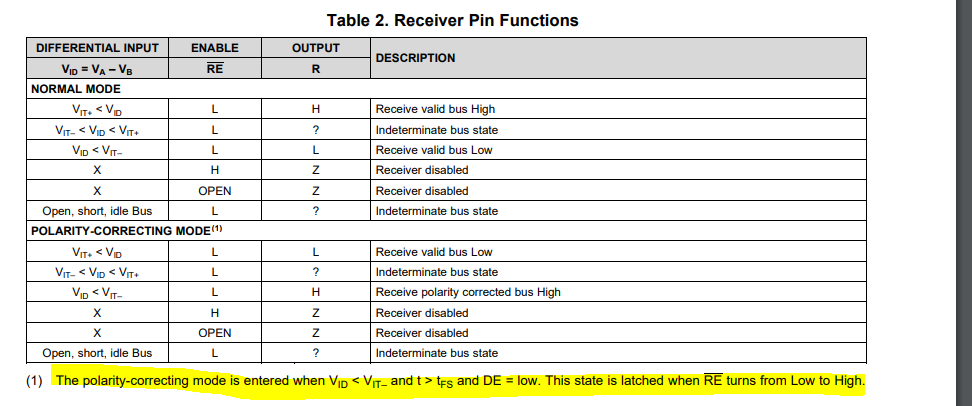
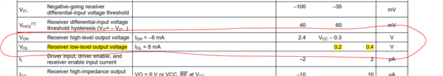
Customer want test and verify VOH and VOL of SN65HVD888, can you show me the specific test circuit for these two parameter?
how to set the Peripheral circuit and adjust IOL(8mA or -8mA as show in DS)?
Hi colleagues,
Customer want test and verify VOH and VOL of SN65HVD888, can you show me the specific test circuit for these two parameter?
how to set the Peripheral circuit and adjust IOL(8mA or -8mA as show in DS)?