This thread has been locked.

If you have a related question, please click the "Ask a related question" button in the top right corner. The newly created question will be automatically linked to this question.

TXS0104E I2C Voltage Level issue

Other Parts Discussed in Thread: TXS0104E, TCA9800, LSF0102

Hi,

We are using this part for I2C Level Translation.

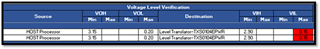
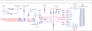
Our Host Processor Works on 3.3V and Slave IC is on 1.8V. That is why we used Level Translator here in between. Please refer to the below schematic.

But we found here Communication is failed.

When I use TXS0104E, it's I2C Waveform in our board is as below and below is our observations.

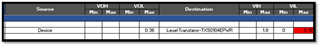
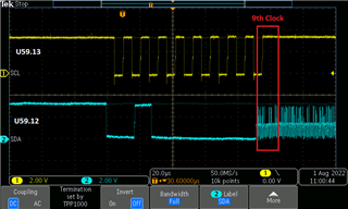
  1. Low Voltage (VL) of both SCL and SDA is not absolute zero here, there is 0.36V.
  2. During the 9th clock pulse, the slave is trying to pull the bus low, and due to the 9th clock extension SDA also retaining in LOW.

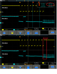
And below is the I2C waveform of U59.13 and U59.12 pin.

Kindly suggest solving this issue.

Regards,

Chitharanjan

  • The TXS has internal pull-up resistors; you should not need external ones.

    The TXS is a passive switch, so it does not reduce the low voltage of any signals.

    Apparently, there is ringing on the line that causes the edge accelerators to trigger. Do you have long traces, connectors, or cables?

  • Dear Clemens

    We have removed the external pullup resistors and tried, but the issue remains the same.

    The below image shows the I2C routing which is routed as a daisy chain topology. The red line indicates the I2C line (SCL & SDA) routing.

    Green BOX indicates -U59 IC

    Red BOX indicates -U67 IC

    Flow : Processor-> Accelerometer IC-> Battery Charger IC -> Level Translator IC -> RTC Controller IC -> Buffer

    And between the U59 and U67 we have provided a short trace length. FYR, please check the below image.

    Please let me know how we can limit these ringing.? are the pullup resistors tuning can help?

    Regards,
    Chitharanjan
  • Apparently, these traces are too long for the TXS. Consider a level shifter without edge accelerators like the LSF0102, or an I²C buffer/level shifter like the TCA9800.

    What is that other I²C buffer?

  • Dear Clemens,

    1. Since our boards are already fabricated and assembled, is there any footprint compatible and without edge accelerators alternate part for TXS0104E?

    2. Whether external resistor pullup tuning can help out to limit this kind of ringing?

    3.I2C buffer (TXS0102DCUR) is used if the I2C lines are taken out from the board through a cable harness. Currently, this circuit is not populated in the design.

    4. Also can you please clarify this TXS0104QPWRQ1 part? Is this the right part without 'E' after the 104? because this part is used in one of our customer EVK.Please clarify.

    Regards,

    Chitharanjan

  • 1. No

    2. The pullups have no effect on that; the ringing is caused by the capacitance and inductance of the traces.

    3. The "E" has no meaning. Anyway, "TXS0104QPWRQ1" is not a valid part number; "TXS0104EQPWRQ1" or "TXS0104EPWR" would be.

  • Hi Clemens,

    Sorry for the delay in reply……

    We have done some experiments on the TXS0104 level translator with different manufacturing batches. The observation is as below.

    1. With the part number TXS0104EPWR and with the below top mark, some parts are working fine and some are not working (facing the issue as mentioned earlier)

    a.TOP MARK

    YF04E

    03KG4

    A2DE

     2. With the part number TXS0104EQPWRQ1 and the below top mark, All the parts are working fine. We have never found any issue with this part.

    a.TOP MARK

    O4EQ1

    1AKG4

    A125

     3. With the part number TXS0104EPWR and with the below top mark, All the parts are working fine. We have never found any issue with this part.

    a.TOP MARK

    YF04E

    09KG4

    DOTF

    So, please let me know what could be the issue with this batch.?

    Also, we have made the electrical verification for the level translator to the device and the Level translator to the HOST processor. Here, we found that the VIL level of the Level translator is not matching on both sides, Either during communication from the device to a Level translator or HOST processor to the level translator.

    In general even with other Host, other slave devices, there is a level mismatch in terms of meeting this very low VIL (Max). Let us know your comments wrt this level mismatch. Is this considered to be a violation?  If so, what are the ways to meet the voltage levels of the host & slave devices?

    1. When HOST Processor to the Level translator

    2. When Device to Level translator

    Please verify and let me know your feedback."

    Regards,

    Chitharanjan

  • Apparently, the capacitance/inductance of your traces is right at the edge of being problematic. It is plausible that small manufacuring variations can affect this.

    The TXS does not buffer signals. See [FAQ] Why are the TXS01xx VIH/VIL specifications so stringent?