This thread has been locked.

If you have a related question, please click the "Ask a related question" button in the top right corner. The newly created question will be automatically linked to this question.

MAX3232: MAX3232: Not getting any output from the converter

Part Number: MAX3232

Hi Experts, 

Good day. I am posting on behalf of the customer.\

Below is the customer's full transcript of the inquiry.

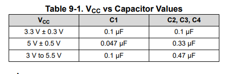
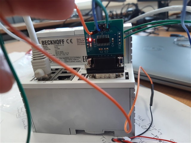
"I need help understanding how the MAX3232 IC works. We are using a Gateway/Converter with the MAX3232 IC from Texas Instruments in One of our Projects. The converter is supposed to converter Between TTl/RS232 Protocols

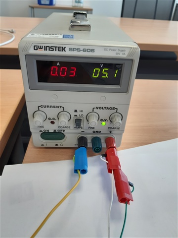
I am not getting any output from the Converter even tho the Converter is receiving data.

This is the converter we are using: https://www.pollin.de/p/rs232-ttl-wandler-mit-max3232-810358?utm_source=google&utm_medium=fshopping&gclid=EAIaIQobChMIt6rq35aX8gIVXAaICR119wLxEAQYAyABEgKB-PD_BwE"

Thank you for your help.

Kind regards, 

Marvin

  • Hi Marvin,

    I have a few questions (highlighted in yellow) if you could help answer for me that would be greatly appreciated!

    What pins are being sent data and which pins are not responding as expected? 

    What voltage supply is being used? 

    It seems that all the capacitors being used are 0.1uF - which is only correct for 3.3V +/-10%. 

    The capacitor table for the voltage ranges are shown below:

    These capacitors are going to be used by the charge pump so if that's incorrect the RS-232 outputs could be incorrect. 

    Is there any specific questions on operation of the part beyond it not working?

    Has the problem been seen on more than one board? 

    Please let me know so I can see if this could be the issue and determine what next steps could be.

    Best,

    Parker Dodson

  • Hi Parker, 

    Good day. Thank you for your quick reply.

    Please see input from your customer.

    "Thank you for getting back to me so quickly. A brief description about Project the MAX3232 Converter is supposed to translate the TTL voltages sent by the Coulomb Counter (referred as CC from hereforth) to the RS232 Voltage levels used by the Beckhoff PLC.
    The CC we are using sends a data packet of 18 bytes every second to Converter which has been confirmed with a oscilloscope. The data packet is as follows :
    www.mylithiumbattery.com/.../TTL232-CC-Comm-Specs.pdf
    The problem occurs on the CC to PLC side where the output TX pin of the DB-9 Pin connector of the Converter. After checking with the oscilloscope the Output pins is constantly outputting -0.8 Volts."

    To answer your questions :
    1) The GND and TX pins CC are connected to the GND and RX pins of the

    "The GND and TX pins CC are connected to the GND and RX pins of the Converter as Shown in the first photo. Since there is no VCC wire coming from the CC itself, thee VCC pin of the Converter is supplied with a 5 VDC supply using an external Laboratory power supply as Shown in the second picture. So from what I understood is that the Converter needs to be supplied with a 3.3 V powersupply instead of a 5 V.

    Also I had a few question, If the RX LED is blinking Red signalling the reception of data, then shouldnt the TX LED also light up immediately even if the Converter is sending false data?
    Also if the Converter is not connected to the PLC and only connected on the CC side, Can we still sense the data at the DB-9 pin connector using the oscilloscope?"

    Thank you for your help.

    Kind regards, 

    Marvin

  • That board does not connect the pins of the second channel. To prevent DIN2 from floating, connect the square pad to GND.

    All capacitors are 100 nF, so you should use a 3.3 V supply.

    The two images did not attach.

  • Hi Marvin,

    Could you please attach the pictures again so I can verify I am understanding everything correctly? 

    From what I can answer - yes due the cap values (100nF each) the device is meant to have a 3.3V supply - if a 5V supply is still wanted the quickest change would be to remove C2/C3/C4 and change them each with a 0.47uF (470nF) capacitor. If 3.3V only is okay no modification is needed.

    Clemens is correct to identify that DIN2 if not used is floating which could cause DOUT2 to oscillate - so while I don't think this is the issue - this is best practice as I don't think the TTL  needs to RX and two TX wires. Only 1 RX/TX goes to the DB9 connector.

    Unless something is different in the picture that didn't seem to get attached - the Diode on the R pin will light up any time a logic 0 is received  and the Driver diode will light up when ever a logic 1 is received. Depending on data-rate and bit-pattern  during transmission these could be "solid" lights. But they aren't connected (i.e. if the driver is held high while data is being received then the diode shouldn't be lighting up. 

    Please let me know if you can reattach the pictures and I will check that as well!

    Best,

    Parker Dodson

  • Hi Parker, 

    Good day. Thank you for the quick response.

    Please see the attached photo provided by the customer.

    Thank you for extending your help.

    Kind regards, 

    Marvin

  • Hi Marvin,

    Thanks for attaching the pictures - it makes sense to me now.

    The TX diode will only light up when the output is driven low - so it seems to be high at this point. 

    Was the customer able to implement any of the suggested fixes? If yes - were the results better?

    Best,

    Parker Dodson