This thread has been locked.

If you have a related question, please click the "Ask a related question" button in the top right corner. The newly created question will be automatically linked to this question.

DS90UB927Q-Q1: DS90UB927Q-Q1&DS90UB928Q-Q1 applied in camera link(80bit mode)display abnormal

Part Number: DS90UB927Q-Q1
Other Parts Discussed in Thread: DS90UB928Q-Q1, DS90CR287

Hi Team,

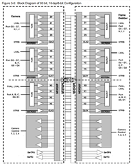
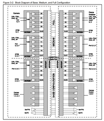
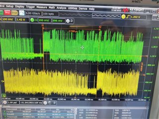
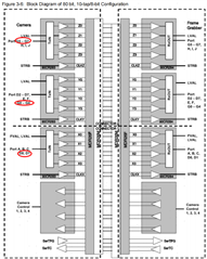
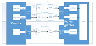
    I used DS90UB927Q-Q1 and DS90UB928Q-Q1 for camera link cable;As you know, camera link has those work mode like base/medium/full/80 bit mode. when the ICs work in 80 bit 10tap8bit mode, image display abnormal.

The abnormal display is as follow. 

I would like to ask you two questions as follow:

1.Do  DS90UB927Q-Q1 and DS90UB928Q-Q1 support camera link working in 80bit 10tap8bit mode?

2.If the ICs cannot support the 10tap8bit mode, Do you have any other chipsets to recommend for camera link 10tap8bit mode?

Thanks!

best regards

DonCheng

  • Hello Don,

    Could you clarify what you mean by "80bit 10tap8bit mode"?

    The 927 accepts LVDS input, with an input PCLK frequency ranging in-between 5-MHz to 85-MHz. In Low-Frequency mode (LFMODE = 1), the supported input PCLK applied at the RxCLKIN+/- pins is between 5-MHz to 15-MHz. If Low-Frequency mode is turned off (LFMODE = 0), then the supported PCLK input is 15-MHz to 85-MHz.

    If there are artifacts on the received video on the display, my first suspicion would be that there is some issue with the input to the 927 serializer. It might also be possible that there are errors introduced onto the video data over the cable link. 

    Are you able to run PATGEN on the 927, to see if any artifacts appear on the display?

    Are you also able to verify the jitter on the input RxCLKIN+/- pins is meeting the datasheet specs?

    Best,

    Justin Phan

  • Hi Justin,

    80bit 10tap8bit mode is shown in the following attaching picture. A port transports 8bit data. 80bit 10tap8bit mode means at one of clock can transport 80 bit data, that is port A to port J. But port D and port G‘s 8bit data is separated into three IC to transport.

    Basically, the direction of video data transmission is as follow:

    Camera(DS90CR287)  -> UB927 ->UB928 -> Frame Grabber(DS90CR288) ->Display

    UB927 and UB928 are applied in full mode application(diagram is shown in the following picture), the video data transports well, aslo the display is OK.

    Are you able to run PATGEN on the 927, to see if any artifacts appear on the display?

    Are you also able to verify the jitter on the input RxCLKIN+/- pins is meeting the datasheet specs?

    NO, we cannot verify neither of them. we don't have PATGEN test tool and it seems that UB927 and UB928 are unable to do the eye diagram test.

    could you please provide a PATGEN test kit for me? thanks.

    Regarding the abnormal display in 80bit 10tap8bit mode, do you have any suggestions for me to do validations? Thanks!

    80bit 10tap8bit mode diagram :

    full mode diagram:

    Best Regards

    Doncheng

  • Hello Don,

    PATGEN is a feature that is built-in to the 927 device. You can enable it to generate a test pattern image, which will be sent to the display instead of your camera input. See the below App Note for more details on what registers to set to configure PATGEN:

    https://www.ti.com/lit/an/snla132g/snla132g.pdf

    If you are getting the expected test image appearing on the screen, then the link between the UB927 ->UB928 -> Frame Grabber(DS90CR288) ->Display has a low chance of having an issue. But since you said that you are able to get your application working in "Full Mode Application", then I doubt that the connection between the UB927 and UB928 is an issue.

    The next thing that you can try is to measure the RxCLKIN+/- pins on the 927 device, to see if it meets our required datasheet specifications.

    If your system does meet these jitter requirements, then it is likely that there is no issue between the DS90CR287  -> UB927.

    Next, you should probe the inputs to the DS90CR287 device and confirm that all of the inputs meet the required switching characteristics.

    As long as the input into the DS90CR287 and UB927 devices meets the datasheet requirements, then our system should support your 10-tap/8-bit configuration.

    Best,

    Justin Phan

  • Also, in your 10-tap/8-bit configuration, discoloration on the display may be due to improper mapping of bits.

    Can you confirm the following:

    1. In the 10-tap/8-bit configuration, the camera is outputting 28-bits of LVCMOS data and feeding it into the DS90CR287 device. The DS90CR287 will output the data in the form of LVDS, with the following mapping:
      1. Based on how the DS90CR287 maps input data to output data, can you confirm that the 10-tap/8-bit configuration will have the exact same output from the DS90CR287 device as in the Full Mode Application?
    2. The UB927 maps incoming LVDS data to LVDS output data on the connected UB928, according to two different mapping schemes:
      1. In the 10-tap/8-bit configuration, can you make sure the mapping scheme that is chosen through the MAPSEL pin on the UB927 still applies and matches what your display is expecting?

    Best,

    Justin Phan

  • Hi Justin,

    Sorry for this delay.

    We are unable to measure UB927's output jitter. But the signal from UB927's input to UB928's output seems OK. the measure is as follows.

    The green is input and the yellow is output.

    More details about the ICs configuration:

    1.In this case, both UB927 and UB928 sides's MAPSEL pins are set low. In my opinion, keep both sides in a same level status, Ser and Deser ICs will work fine.

    2.Both UB927 and UB928 sides use the default I2C configurations. Will it be the source of the abnormal display.

    3.Under the above two conditions, cable link works fine in base/medium/full mode except the 80bit mode.

    4.In 80bit mode working in 65MHz clock which has lower data rate than in full mode working in 82MHz clock, however 80bit mode display  is abnormal and full mode is normal.

    Best Regards

    Don Cheng

  • The main difference between full mode and 80bit mode is that port D and port G's 8bit data is separated into three ICs to transport in 80bit mode, when using UB927 and UB928 as cable link  in this application,  Will this affect data reassembly on the receiving end?

    BR

    Don

  • Hi Justin,

    BTW, I have two more questions for you: 

    1.For UB927 and UB928, is there a register that I can get the data rate between UB927 and UB928?

    2.For UB927, without any input video data, why is there serial output when UB927 is powered on?

    BR

    Don

  • Could you clarify where the 927 and 928 devices are in your system? I'm still having a bit of trouble trying to picture your full system.

    1. There is not a register that will record the line rate between the 927 and 928.
      1. The Forward Channel line rate depends on the frequency of the input PCLK to the 927:
    2. 92x devices typically have an internal always-on (AON) clock that can be used to maintain a Forward Channel or Back Channel link, in the absence of an active PCLK input, in order to enable I2C communication. 

    Best,

    Justin Phan

  • Hi Justin,

    As is mentioned previously, UB92x is applied in Camera Link and its specification is formulated by 3M Co.

    Camera Link spec is attached. There is a detailed introduction to each configuration like base/medium/full/80bit in the chapter 3 of spec.

    UB92x is used as a connecting cable between camera and frame grabber.

    Connecting camera and frame grabber with copper wire, the display working in base/medium/full/80bit mode is normal. while using UB92x as a connecting cable, cable link works fine in base/medium/full mode except the 80bit mode.

    what I want to know from you is as follows:

    1.Do  DS90UB927Q-Q1 and DS90UB928Q-Q1 support Camera Link working in 80bit 10tap8bit mode?

    2.If the ICs cannot support the 10tap8bit mode, Do you have any other chipsets to recommend for camera link 10tap8bit mode?

    Thanks.

    Best Regards

    DonCheng

    Camera_Link_v2.0_Feb10-2012_final_cameralink标准协议.pdf

  • Hi Don,

    My main confusion is the specific connections that were made between different FPD-Link devices and what is the specific input to the 92x devices used in your system. If the input to the 927 device is within datasheet specifications, then our devices should be able to work as intended.

    It seems you have a camera module with a built-in DS90CR287 chip that will convert 28-bit parallel video data it receives from the camera into 4 LVDS output video streams, using the mapping below:

    You are then feeding the 4 LVDS outputs from the DS90CR287 into the 927 serializer, where it will be sent to the 928 deserializer over a cable link.

    Is the difference between the Base/Medium/Full setups the fact that 1 camera is used in the Base setup, which is connected to a single 927/928 pair, and that the Full setup uses 3 cameras, where each camera is connected to a separate 927/928 pair?

    If so, then each camera will output 24-bit video data + 4-bits sync data and that will be transferred over the 927/928, using the MAPSEL=LOW setting.

    If the camera is configured for 10-taps/8-bit mode, is the hardware the same? If so, how would the 28-bit parallel data output be mapped to the inputs of the 927 serializers?

    I am looking into the document that you provided, but if you can provide any additional clarifications or diagrams, then that would be beneficial too.

    Best,

    Justin Phan

  • Hi Justin,

    Is the difference between the Base/Medium/Full setups the fact that 1 camera is used in the Base setup, which is connected to a single 927/928 pair, and that the Full setup uses 3 cameras, where each camera is connected to a separate 927/928 pair?

    Not 3 cameras. Only one camera that contains 2 connectors for cable link is used in this system.

    there are 2 cables connecting camera and frame grabber. For base cable, there is 1 pair of 927/928. For full cable, there are 2 pairs of 927/928. the application diagram of the system is as follows:

    If the camera is configured for 10-taps/8-bit mode, is the hardware the same? If so, how would the 28-bit parallel data output be mapped to the inputs of the 927 serializers?

    Yes, both full mode and 10tap8bit mode has a same set of hardware. For 10tap8bit's 28bit parallel data out, in my opinion, all video data coming from the DS90CR287 may have the same output data format like this:

    I have the same confusion with you and haven't seen any data output format about 10tap8bit in this spec.

    Looking forward to your reply.

    Best Regards

    DonCheng

  • Hello Don,

    I will need to look into the documentation a little more and provide comments within ~1-2 business days.

    Best,

    Justin Phan

  • Hello Don,

    Is there someone from the camera manufacturer that you can reach out to, in order to confirm the parallel video pin mapping of the camera when it it configured for Full Mode vs. 10-Tap/8-bit Mode?

    My understanding is that Section 4.1 and 4.2 in the document you shared with me do describe the bit mapping. A port is defined as an 8-bit word, so a port should represent 8 parallel data lanes from the Camera to the DS90CR287 device. Ports A, B, and C should represent 24-bit RGB parallel data lines into the DS90CR287 labelled Chip X. There are also 4 signals leading into the DS90CR287, which should stand for HSync, VSync, DE, and Spare.

    The Full Mode configuration seems to work because the mapping aligns with how our 927/928 devices map the RGB bits in the LVDS stream. See example below:

    In the Full Mode setup, if you look at the green highlight in the figure, it seems that Parallel Video pin TX/RX21 outputs data labelled "PortC4", which must either be an RGB value of some sync bit. The DS90CR287 will map the parallel video in the LVDS format in the upper-right image, where PortC4 is mapped to the TxIN21 slot. The 927/928 will treat that TxIN21 slot as one of the blue bits in the RGB data being sent from the camera (B[6]). 

    If the TX/RX21 pin on the camera is outputting bit 6 of the 8-bit Blue video data, then all of the mapping matches and you will get your expected video display. If the mapping does not match, then one likely symptom is that your display will show a discolored image, since you are not mapping the RGB data correctly.

    These are all assumptions on my part, since I am not familiar with the camera module being used. The 10-tap/8-bit setting seems to send different RGB data bits to different parallel video pins on the camera.

    If you have a question on the TI part, I can help answer, but this seems like a question you need to ask the camera manufacturer and you should confirm what video is being outputted at each pin of the camera in the different modes.

    Best,

    Justin Phan

  • Hi Justin,

    Understood. Thanks for your patient support. 

    BTW, Is there a register of 927 or 928  to record the data rate change?

    Best Regards

    DonCheng

  • Hello Don,

    The Forward Channel line rate is directly related to the PCLK input and the MODE the device is in. There is not a register that will record the PCLK input frequency or the line rate. If you need these values, then you will have to calculate this by hand.

    Best,

    Justin Phan