Part Number: DP83822IF
Other Parts Discussed in Thread: DP83822HF, DP83822EVM
Hi.
I've been working on this for several days.
I want to make the optical LINK-UP work between a 100 BASE-FX planet converter device & a 100 BASE-FX SFP that is connected to DP83822HF on the DP83822EVM.
I made sure every components in the SFP section of the EVM were correctly soldered on the board except for the AC coupling caps, since they are already included in the SFP module.
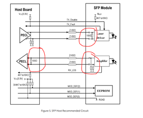
Here is the module's datasheet : https://img-en.fs.com/file/datasheet/sfp-100fx-31-i.pdf
Here is a screenshot from the module's recommended connections :

I also made sure that either mode 2 or mode 3 was forced on pin COL to activate the 100BASE-FX.
Since SFPs SD pin is LOS (SD#) instead of SD, I've inverted the the LOS signal on the EVM ( patching an inverter ) on the board to make sure it was active high.
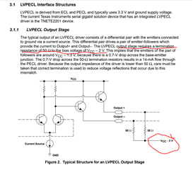
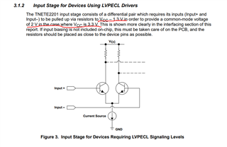
I've read somewhere that the DP83822's 100BASE-FX physical media output pins were LVPECL. I than read on a TI application note (https://www.ti.com/lit/an/slla120/slla120.pdf?ts=1659557299886&ref_url=https%253A%252F%252Fwww.google.com%252F) that the LVPECL specs were as follow :


So knowing that, the common mode voltage of transmitter pins should be around 2V while the Common mode voltage of receiver pins should be around 1.3 V. The thevenin impedance should be around 50 Ohms. I should then logically solder 4x 82 Ohms & 130 Ohms resistor dividers on the transmitter & receiver pins to make it work.
However, looking at the DP83822 EVM, no terminations are provided, except for the 50 Ohms Pull ups to 3.3 V. Is there something that I'm missing ? Is the 100 BASE-FX transceiver circuitry present in the DP83822 really LVPECL ? Is the receiver bias circuitry integrated into the chipset ? Why would 50 Ohms pull ups be required for the receiver too ? It does not corresponds to LVPECL specs...
Thank you very much for your help.
Pierre Robitaille

