


Part Number: SN65MLVD204A
Dear team,
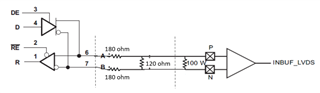
Customer would like to use the SN65MLVD204A driver (on the transmitter side, single-ended signal on its D input, supplied with 3.3V) to an IC which has an LVDS input.
In order to adapt the M-LVDS output of the SN65MLVD204A, an attenuation network has been placed: see diagram below, network with 2 series resistors of 180ohm and a parallel resistor of 120ohm.
They implemented this network and with these resistor values they get a differential voltage of ~380mV for a common mode voltage of 0.8-1V. Which is acceptable.
Previously, they tried with the following network : 2x158ohm (series) + 158 ohm (parallel) and the measured differential voltage was 450mV. Which is too marginal.
They would like to have, if possible, the necessary information on the SN65MLVD204A allowing them to confirm theoretically that the resistor network gives the expected results.
They imagine that in "normal" operation, the device works as a current source. Operation made impossible by the addition of this network?
Thanks in advance for your support.
Pol.

