This thread has been locked.

If you have a related question, please click the "Ask a related question" button in the top right corner. The newly created question will be automatically linked to this question.

SN65HVD3085E: terminal resistor effect

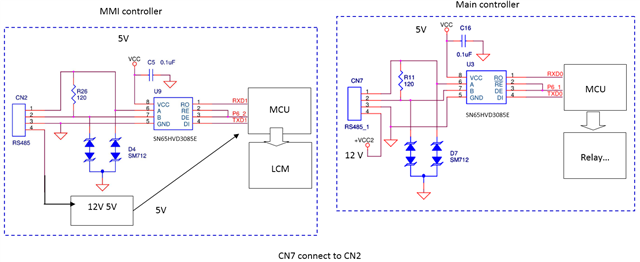
Part Number: SN65HVD3085E

As stated above, we find there are two failure modes about the RS485 ICs.

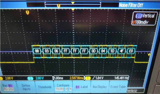
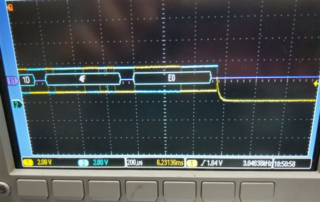
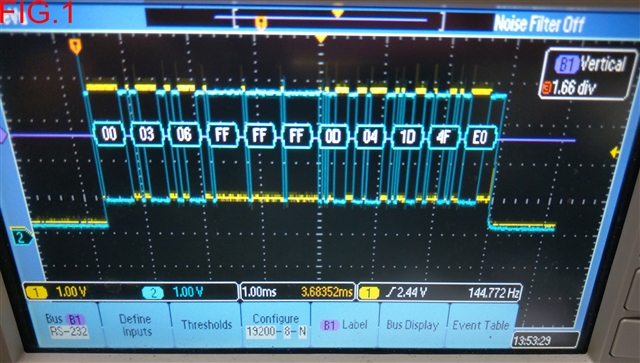
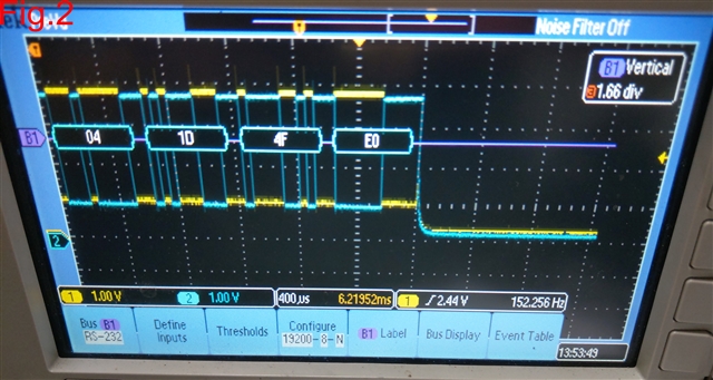
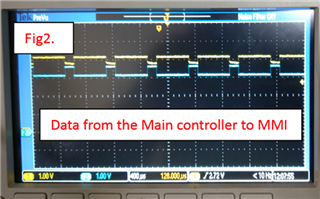
The failure mode happened on the main control board is that the 485 IC can receive the data correctly, but the driver function is abnormal. No data or abnormal data(Fig.2) is on the RS485 bus when the IC is at driver mode.  We think the RS485 ICs on the main controller are failed actually. Those curves are DA to DCG, DB to DCG.


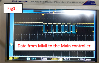
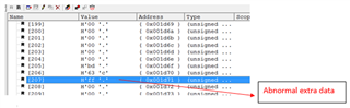
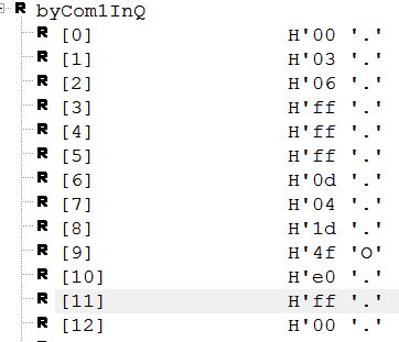
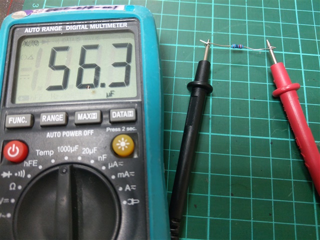
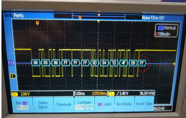
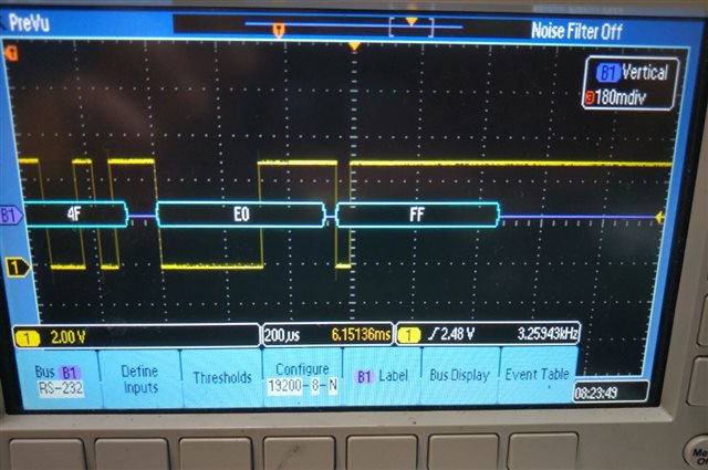
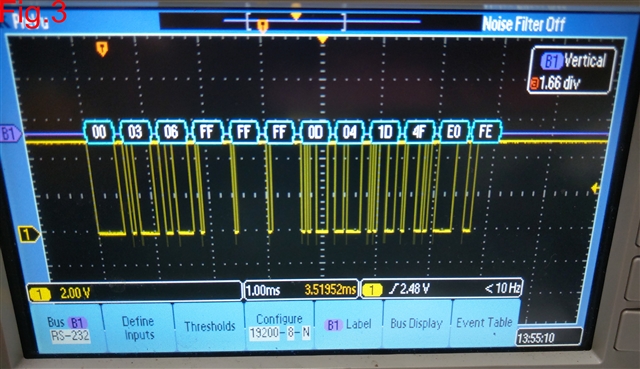
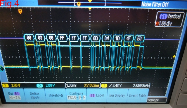
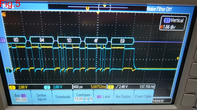
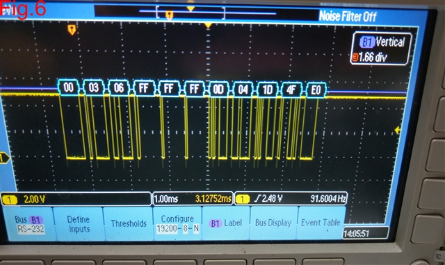
The failure mode happened on the MMI controller is that the MMI controller can not receive the data correctly.  We find the MMI controller can receive data, but there is one byte(0xFF) more or one byte less at the end.  For example, the correct count is 207 bytes, but the MMI controller will receive 206 or 208 bytes.  When we remove the terminal resistor (120 ohm), the MMI controller can receive the data correctly.  The distance between two controller is about 1.5m.  Now our one question is that why the resistor affects the receive function on the MMI controller?  Is the RS485 IC on the MMI normally?   

  • Hi ccKevin,

    Do you have a schematic snippet of the RS-485 portion of the application that you can share? I understand if you can't  - but please let me know if you can - it will help me get a better idea of the system and it could possibly help explain the issues you are seeing. 

    I have a few other questions to try to understand the problems you are seeing.

    Problem #1 - Strange Driver behavior

    1. Is the data in figure 2 supposed to match the data in figure 1? If so is it possible to see the scope shots on the same time scale and could you confirm the data rate for me?

    2. Understanding how the device is controlled would be helpful - is there a signal controlling the driver enable or is it always active? 

    3. How many termination resistors are used in the system - it seems there is at least 1 120 Ohm termination resistor. Is there anything else on the bus that could be loading the driver besides the termination resistors? 

    4. If the signal path is 1.5meters in this problem scenario as well - I don't think it should be that much of an issue - but do you know the capacitance of that pathway? (I doubt this is a major issue if its 1.5meters as that is very short for RS-485 so its usually not a huge impact on the system)

    Problem #2 Receives Correct #number of bytes only with termination removed 

    1. Similar to above - knowing the bus capacitance and any other element that is loading the bus (besides termination resistors - so if there are filtering capacitors/protection devices/fail safe resistors/etc. on the line) as well as the intended datarate would be helpful to know.

    2. How many termination resistors are originally placed in the system? I know 1 is there for sure - but are there more? (RS-485 typically suggests termination resistors so I just want to check to see how many were in the system) 

    3. Is the signal coming to the MMI controller from the problematic driver? If so the issue could be tied back to issue 1 - having a logic analyzer or a  differential scope probe on the receiver could help determine if the the receiver is actually having issues receiving data or if the driver sending data is having issues with the termination. 

    The issue at the receiver could be caused by multiple things such as the driver, or the loading, or possibly the receiver - but the receiver is largely just a comparator so my guess is that this problem is probably related to problem 1 which could be driver issues due to bus loading.

    What I will say however - in a 1.5 meter system generally you don't need termination for it to function properly, its still recommended but its not as necessary.

    Please let me know if you can get some of this information and I will see what I can do to look deeper into the problem you are having!

    Best,

    Parker Dodson


  • Dear Parker,

    1. Our circuit is as follows. The MMI can hot plug into and plug out the RS485 port of the main controller.  

    2. I answer your questions as followed.

    2.1 Problem #1-1: The data in Fig1. and Fig. 2 are from the same MMI and main controller.  The main controller is problematic.  We use the Modbus RTU protocol.  The MMI is master, and the main controller is slave.  Fig.1 shows the data from MMI to main controller, the curve is normal.  Fig.2 show the data from main controller to MMI, and is abnormal.  The baudrate is 19200 bps.

    2.2 Problem #1-2: The MCU will control the DE/RE signal.  I think the signal is correct because we don't change the software code during we do those test. 

    2.3 Problem #1-3: As the circuit above, there are two 120ohm and two SM712 on the bus.  

    2.4 Problem #1-4: I don't know the capacitance of the pathway.  How can I measure it?

    2.5 Problem #2-1: as Problem#1-3.

    2.6 Problem #2-2: two terminal resistor

    2.7 Problem #2-3: When we test the MMI, we use the normal main controller which can communicate with most MMIs.  When we test the main controller, we use the normal MMI controller.  

    3. We observe one phenomenon.  Some problematic main controller had plugged in/out the MMI severval times.  We check the datasheet, the SN65HVD3085E can be used for Hot plug appilication. Is right? 

    Thanks for your help.

  • Hi ccKevin,

    Thanks so much for the detailed response!

    I understand the setup much better now - and from a schematic perspective I don't see too much issue here - the diodes are specifically for RS-485 devices and they don't add too much capacitance (about 150pF since there is 1 diode at each node - which shouldn't be too bad).

    For capacitance of the line it depends on the transmission medium. Is it a cable that connects the devices or is it a microstrip trace (so just normal copper trace?). If a cable is used it should have a capacitance per unit length in the cable's datasheet. If it is a transmission line the capacitance is just the parallel plate capacitor formula:

    C = (εo*εr*A) / d - where εo is the permittivity of free space constant, εr is the permittivity constant of the dielectric material between the trace and ground plane, A is the trace's area, and d is the dielectric thickness. 

    but unless the capacitance is really high I don't think it should cause too much issue because you have a very short length of the bus and the data-rate is slow. 

    Just to make sure I understand - there are only two nodes correct (MMI controller and Main controller) or are there multiple controllers that the RS-485 devices are communicating on?

    As for hot-swapping; it depends on what pins are exposed to voltages. If it is just the A/B pin that are being exposed to the voltages, which I would assume to be the case in this application, as the A/B pins are rated from -9V to 14V for fault protection, and when stable supply is detected we recommend the typical -7V/12V rating (for common mode voltages). However not all the pins are "safe" in this event - if the R/DE/ /RE / or D pins are exposed to voltages above VCC (i.e. if the MCU somehow has  a signal on any of those pins before that is above the VCC received by the device as they have ESD diodes to GND/VCC connections that can cause Electrical overstress damage if the voltages at these pins are exposed to less than -0.3V w.r.t. ground or VCC + 0.3V w.r.t. ground. For the A / B pins though it shouldn't be that much of an issue (as long as the voltages w.r.t. to the connected transceivers ground does not violate the fault protection ratings of the device).

    For the suspect receiver can you measure the A to B voltage in the case where the termination resistor is removed and when it is installed - since the controller sending data has been verified as "good"  as I'd like to understand how that signal is changing because the receiver typically doesn't have too many problems so understanding how that is loading the signal would be helpful. 

    How many devices are failing out how many have been tested? Was there ever good data from these parts or was there a failure after running testing? As it may be possible that some electrical overstress damage occurred but it really depends on what tests were being performed and what pins were exposed to what voltages at what time. 

    Please let me know!

    Best,

    Parker Dodson


  • Dear Parker,

    I use the digital multimeter to measure the capacitance.  When there is one 120 terminal resistor, the capacitance between the A/B Pins without the cable is 58uF, the capacitance with the cable also is about 58uF.  Do you think the capacitance is acceptable?  When there is not the 120 ohm resistor, the capacitance is zero. 

    In our application, only one MMI will connect to the main controller.

    The following picture is the data from the main controller to the problematic MMI, and there are two resistors at both side.  On the oscilloscope, the data is correct.


    The detail scope of the end is as follows.


    But the main controller will receive the data as follows.  The byte[11] is an extra data.

    Provide the above information.  Can you find some problem?

    Thanks for your help.  

  • Hi ccKevin,

    So - I just want to confirm - that the capacitance is 58uF. If that is true that is most likely the issue. 

    With the resistance of the bus + termination + capacitance you are looking at a few problems:

    1. Data reception is too slow due to high bus time constant

    2. The driver has issue driving the line because of the capacitance - even at only a baud rate of 19200 bps will create a low impedance pathway through the capacitor. 

    However I do suspect that the capacitance measurement may be a little high because you seem to still be receiving some data. However too much bus capacitance still may be the issue - as in long cable RS-485 systems we typically test with a cable that would be eq. capacitance in the nF range at 1km - so uF range is a ton of capacitance w.r.t. to these types of applications - if the value truly is 58uF that has to be reduced - either through a different cable setup or possibly different layout.

    Please let me know if that is the correct capacitance value- because if it is that is most likely the issue. If you have a part number for the cable that is being used that would be super helpful so I could also take a look at the cabling.

    Bes,

    Parker Dodson

  • Dear Parker,

    I measure a general 120 ohm resistor, its capacitance is 56.3uF.  The 120ohm resistors on the MMI and the main controller are chip resistors(SMD).  We measure the chip resistor, the capacitance is about 56.9uF.  When the controller with 120ohm resistor connects the 1.5m cable, the capacitance between  Pin A/B is about  58uF.  I think the capacitance is provided by the resistor.  But, is there a 120ohm resistor with low capacitance?

    Another information is that when we measure the signal on the R pin pf the problematic RS485 IC, there is an extra data really.


    Another information is that not all RS485 ICs(SN65HVD3085E) have the problem, and somtimes but rarely the problematic RS485 IC can work correctly.

    Can you give me some advice?

    Thanks for your help.

  • Hi ccKevin,

    I think the meter you are using isn't measuring the capacitance correctly - the through hole resistor shouldn't have 58uF of capacitance - and if it did you wouldn't be reading any data and usually the parasitic capacitance of a through hole resistor is  not uF - the impedance would be less 1ohm at that point and driver cannot drive that and it wouldn't show up.  A 58uF capacitor is generally pretty large (bigger than that resistor itself) - essentially that resistor is too small to physically have that much capacitance. 

    The cable that is being used - does it have a part number - as it's capacitance will be listed and I don't think the measurements are correct - but that could be part of the issue. 

    I am concerned about the amount of capacitance on the bus - but I don't think its nearly as high as you are measuring due to how the circuit is reacting (it wouldn't react this way under that high of a capacitance measurement).

    If only a few units aren't working - it may require them to go through our quality steps for returns/possible FA - I don't know if that's necessary - but I do need to have accurate measurements of the bus capacitance - because it could be causing damage to the parts - and if the capacitance is still high that could have overstressed the drivers. 

    Please if there is a part number for the cable that would be very helpful - because the current value measured doesn't line up with the circuit behavior.

    Best,

    Parker Dodson 

  • Dear Parker,

    Because the problematic ICs can work correctly sometimes, we can't find them out instantly.  The problematic ICs will ship to our customers.  It will still be a problem for our end customers. 

    In the thread "SN65HVD3085E: Driver function fail", I explained the situation of our supplier.  Currently, we can't return the problematic ICs to TI by Arrow Electronics. Do you have any solutions to help me analyze the problematic ICs? 

    We try to use the twisted pair cable to do the test.  The twisted pair cable that we used is shown below.  The length is about 1.5m.


    The capacitance of the cable is as follows.

    When we use the twisted pair cable and have two resistors on the terminals, the RS485 bus signals(Fig.1, Fig.2) and RX signal(Fig.3) are shown below.  Fig.2 shows the detailed ending part of Fig.1.  An extra data "FE" is displayed in Fig.3. and causes the problem.

    We use the twisted pair cable and have no resistors on the terminal.  The RS485 bus signals(Fig.4, Fig.5) and RX signal(Fig.6)  are shown below.  Some pulses appear at the start of the signal, but the data(Fig.6) is correct.  The signals having some pulse can be acceptable? 

    Thanks for your help.

  • ccKevin,

    I am not sure why the termination resistors are causing problems - I wouldn't through hole as they are more likely to have issues due to parasitics. 

    However at 1.5 meters with the data-rate you don't need the termination resistors. The cable capacitance is most likely not the issue as its in the pF range (which is acceptable and shouldn't be causing problems)  

    Has there been any fails with the termination resistor removed? If there are no fail cases on the no termination resistor case I'd try problematic IC's with no termination resistor (if not fully done already) - if they don't fail remove the termination resistor. 

    Other than that the other option is for a return to see if there are issues. If that can't be done and the removal of the termination resistor doesn't work there isn't much else I can do - there is nothing wrong from the schematic from what I can see - and it seems that no termination resistor is working. 

    Please let me know if the removal of the termination is possible and if there are any fails in that case.

    Best,

    Parker Dodson

  • Dear Parker,

    1. We will produce one batch of MMI and main controllers which have no terminal resistors, and observe the failure rate.

    2. After removing the terminal resistors, most problematic RS485 ICs on the MMI controller can work normally but a few are still failed.  I think the failure mode is different.

    3. The MMI controller has the terminal resistor issue.  The failure mode on the main controller is different.  We don't know if it is helpful for the main controller to remove the terminal resistors.  

    4. Can we return the problematic ICs to TI directly?  There are some difficulties to return them by Arrow Electronics.

    Thanks for your help.

  • Hi ccKevin,

    You'd have to return them through Arrow since that's where they were purchased - they are an authorized TI distributor everywhere but Japan though so in most cases that should be okay. 

    There could be transients that damage the device that aren't apparent through the schematic - if failures are still occurring without the termination resistor installed a return is the most realistic next step. However I am a bit skeptical as the error you are seeing doesn't seem to align with common damage signs - but I could be wrong. 

    Best,

    Parker Dodson