This thread has been locked.

If you have a related question, please click the "Ask a related question" button in the top right corner. The newly created question will be automatically linked to this question.

DS90UB954-Q1: Technology support for DS90UB954-Q1 and DS90UB953-Q1

Part Number: DS90UB954-Q1
Other Parts Discussed in Thread: DS90UB953-Q1, , TSER953, TDES954,

Hi,

We kick off a new project for the camera communicate with SOC(NXP I.MX 8 MX), and now we have below technology support need from TI;

1. We have below spec. for the camera:

  1) Resolution: 1080*1280;

  2) Frame rate: 100fps;

  3) Color deep: 12bit;

  4) Type: Black & White, 

Please advise if the DS90UB954-Q1 and DS90UB953-Q1 are available or not for this reqest; 

2. What the different between DS90UB954-Q1/ DS90UB953-Q1 and TDES954/ TSER953, and if we can dsign in same schematic diagram?

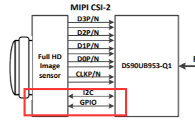
3. We will use the I2C to control the flash lamp , and now the I2C of DS90UB953 is control the image sensor, and please advise if we can add both image sensor and flash lamp mudule on the I2C bus parallelly;

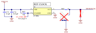
4. We will design the schematic diagram same as the DS90UB954-Q1EVM, and please avise if we can use the crystal instand of the oscillator;

5. If we can use the internal 1.1-V regulator instand the TPS74801TDRCRQ1;

6. How to set the INTB? We have no idea what the situation we need to use the INTB;

7. We only have one camera(one MIPI) , and can we set the CLK0 or CLK1 to control the 4 lans for data transfer?

8. Please advise the BISTEN/ RSVD pin funcation and if we need to connect to GND as the EVM, thanks.

  • Hi,

    Pleaes help to confirm the above issue, we need to finish the schematic diagram this week, thanks.

  • Hey Zhang,

    I can answer a few of your questions. Another engineer will help answer your remaining questions!

    2. The UB parts are part of our automotive portfolio, while the TSER/TDES parts are part of our industrial portfolio. Meaning that the TSER/TDES parts follow industrial specifications. They are pin-to-pin compatible, so the same design can work for either the UB pair or the TSER/TDES pair.

    3. Yes, there can be multiple targets on the I2C bus. Please consider the bus capacitance and calculate the correct pullup resistor value for the design.

    6. INTB is used for interrupt purposes. There is more information in the following section of the TDES954 datasheet: 7.5.8 Interrupt Support. Please let us know if you have any follow up questions on this pin's functionality :) 

    8. This is the pin description for the BISTEN pin: "BIST Enable: BISTEN = H, BIST Mode is enabled BISTEN = L, BIST Mode is disabled. If unused connect BISTEN directly to GND. See BIST section Section 7.5.12 for more information" BIST is the "built-in self test" mode used for testing the link. If not needed, it should be grounded.

    Thanks,

    Lysny

  • Hi Lysny,

    Thanks for youkindly support;

    And the others, please kindly help to review and provide your comment, thanks.

  • HI Zhang,

    Here is the additional information you requested.

    1. This is how I calculated the rate and looks like you can use the 953 and 954 setup but you will needs to send data using 4 lanes.  

    Image Resolution * Fame Rate * Overhead (25%)

    (1080*1280) * 100Hz Raw12 * 25% = 2,074Mbps 

    953 can handle 832 Mbps per lane which would require that you use all 4 lanes. 

    4.Yes, you can use crystal please see section 7.4.5 in the data sheet

    Link to datasheet 

    DS90UB954-Q1 Dual 4.16 Gbps FPD-Link III Deserializer Hub With MIPI CSI-2 Outputs for 2MP/60fps Cameras and RADAR datasheet (Rev. B) (ti.com)

    5. It think you are asking if you can use the 954 internal regulator. Please correct me if I am wrong. 

    Yes, you can see section 8.2 Typical Application Figure43. This show how to setup the system to use the internal regulator. Make sure the VDD_SEL is to ground.

    7. I am not quite sure on the question here. You need to use CLK0 will have the clock output. 

    Glenn