This thread has been locked.

If you have a related question, please click the "Ask a related question" button in the top right corner. The newly created question will be automatically linked to this question.

SN65C1167: short circuit current limit

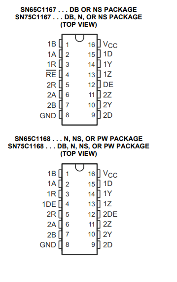
Part Number: SN65C1167
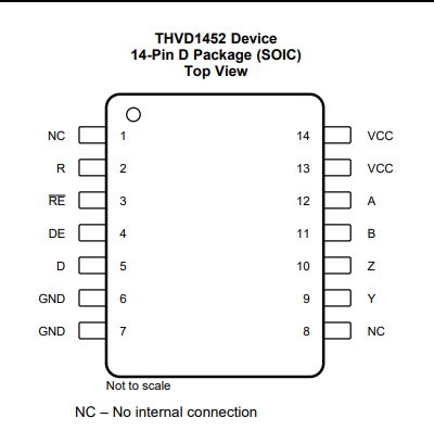
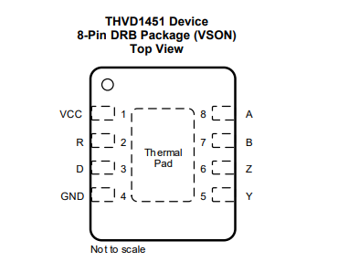
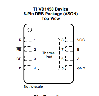
Other Parts Discussed in Thread: THVD1452, THVD1450, , THVD1451

Hi Experts,

We understood that:
1. if one output is shorted for more than one second or
2. if both outputs are shorted.
the component will be damaged.

Our customer wonder the scenario where such conditioned short circuit (like only one output shorted, or shorted for less than a sec) might occur. He said that he might have misunderstood the statement in the datasheet.
They also needed some option for output short protection. Atleast longer than 1sec. We hope that you can help us.

Thank you and kind regards,
Gerald

  • Hi Gerald,

    So all the parts that match this part (full duplex / 2 drivers / 2 receivers ) all have the note of no more than 1 second of a short circuit. 

    So if the same architecture is to be used with TI components a short circuit detection mechanism that resolves the short in < 1 second would be needed. Do you know why the customer cannot respond to a short circuit in under 1 second for the system? 

    That being said - we don't have this note/warning on newer devices, nor typically do we spec an abs max current (we still spec a min/max short circuit current - but its a different spec.) It generally is more based on a case by case basis. The junction temperature is the most concerning parameter during short circuit events as the current can be large enough to heat the junction up pretty quickly - so there is generally a time but it isn't spec'd as it varies a lot based on system parameters. However there aren't options in the current full duplex 2TX 2RX device that is being used that allow for the flexibility that may be needed by the system. As one last note - we don't guarantee a time on most of our other parts - it is more flexible because the concern is junction temperature so it could be estimated.

    Please let me know if the customer is open to a multi-chip solution as I don't think we have a single chip solution that can work in this application.

    Best,

    Parker Dodson

  • Hi Parker,

    Thank you for your kindness in explaining this matter.

    Our customer is trying to reduce the number of chips. Having only a driver (Half duplex/simplex) is also fine for them. They required to have rise time less than 10ns which has short circuit protection or continuous current limit for short. He said that it is output requirement standard they need to follow.

    Kind regards,
    Gerald

  • Hi Gerald,

    Thanks for the quick reply and the information - I appreciate it!

    So with those requirements considered: 

    For the short circuit current - as I said above we don't really  have any parts with an rating past 1 second - its usually not listed on newer devices because its dependent on the environment of the system. Essentially the concern is that the junction temperature - which is typically rated to 150C. The junction temperature can be approximated by summing the power at all pins - generally speaking logic pins are very  low power (D and Enable pins) and if R is disabled it will be Hi-Z which also will have very little power. The issue comes with the Driver pins as they could output +/-250mA of current for RS-485 devices. Using the VOH/VOL graphs (if present) can help you determine an output impedance and you can calculate the power at those pins during a short. Junction temperature than can be approximated by:

    Tj = TA + Power * R_theta_JA; where power is the total power dissipation at each pin. 

    For the rise - time essentially most devices that are 50Mbps from us should be at that rating - but not necessarily (as the current part you are looking at does have a max 10ns rise time at its 10Mbps (this is not common and I have a feeling we may have been a bit conservative on its speed)). 

    With all of those things considered I think we have a couple options to consider:

    THVD1452 in the SOIC package - its a full-duplex device, but only 1 channel. Its R_theta_JA is 86.4 C/W and the THVD14xx family at a 5V supply during short circuit can burn around 1.3W at the driver (based on the VOH/VOL graphs to get output impedance of the driver) so this will add ~112 degrees from the ambient temperature. This can be reduced by using layout techniques and possible adding heat sinks to keep the junction temperature under 150C - as going above is where there could be problems. The max differential rise time is 6ns

    The THVD1450 is another option (in the DRB package) - this device is only half-duplex but has the benefit of a low R_theta_JA of 48.6 C/W with the same output impedance as the THVD1452 so under a short you add ~63 degrees from the ambient temperature - so its possible that extra heat sinking may not be needed.

    I think these are the best options as they are the most realistic devices that may be able to sustain extended periods of short  circuit currents as long as the junction temperature is kept in check - which should be possible depending on environment. One thing to note is that the R_theta_JA of the part isn't static and the system will influence this value (i.e. good thermal reduction techniques in layout/design can improve performance).

    Please let me know if you  have any other questions!

    Best,

    Parker Dodson

  • Hi Parker,

    Our customer would like to request if you could you please tell the multichip solution for the same as you suggested?

    Thank you and kind regards,

    Gerald

  • Hi Gerald,

    Its the same names on the pins so you just need to match the pin names when looking at the new parts - please see current part SN65C1167 - where you could get 2 TX and 2 RX in full duplex:

    THVD1452 (SOIC) This is a 2 chip solution - full-duplex; however it could gain ~112 C from the ambient without heat sinking - its pinout is shown below:

    The pins mean the same thing on both devices - so Z goes to Z, Y goes to Y ... etc..

    This solution would require heat sinking though in a lot of applications

    The next solution is the THVD1451 (in VSON package)  which is one of the best in terms of heating. It is also a 2-chip solution - however the one difference is there are no enable pins - the driver and receiver are always on 

    If the always on feature is not going to work we have another device with the same heating parameters to the 1451. It is the THVD1450 in the VSON package it's a 4-chip solution since it half duplex - that means the A/B pins also function as the Y/Z pins on a full-duplex device. You can create a full duplex system by using 2 transceivers per node - one for RX and one for TX:

    The THVD1450 and THVD1451 in the VSON package would be the best as they have thermal pads which help dissipate a lot of heat. The THVD1452 is possible but there would probably need to be heat sinking added to the application.

    All these parts are found in the same datasheet here: https://www.ti.com/lit/ds/symlink/thvd1450.pdf?ts=1660666142702&ref_url=https%253A%252F%252Fwww.google.com%252F

    All the pins have the same function as the current part so there isn't really any  extra things to consider.

    Please let me know if you have any more questions!

    Best,

    Parker Dodson