This thread has been locked.

If you have a related question, please click the "Ask a related question" button in the top right corner. The newly created question will be automatically linked to this question.

DP83826E Fast Link Down Triggering Thresholds

Part Number: DP83826E

Hi,

We need to understand the triggering and monitoring thresholds for fast link down to make sure our custom ethercat cabling in this motion system that we are designing will be compliant and not "on the edge" or far below expected levels for a fast link down failure.  We have already had problems with this with our existing custom cable.  This is critical to our ethercat system performance.  We will be turning fast link down off during critical windows of operation to reduce the chance of link loss to an absolute minimum, but we would like to leave it on most of the time so we are getting the maximum benefit of the functionality.

My questions are as follows:

1.  Is there a PHY configuration permutation that enables us to actively monitor the Fast Link Down status flags (0x0F in management bus) but not have FLD automatically kill the link?  This would be optimal for us.  Or alternatively, do you only get access to the benefits of the flags in 0x0F when a link drop function is enabled/present?

2.  Bit 1 of 0x0B references a signal to noise ratio detection mode that can trigger a FLD link drop.  What is the actual SNR threshold that will trigger this flag?  We would like to measure the performance of our old cable and the new cable we are designing to make sure it well exceeds the failure threshold of the this feature on the DP83826.

3.  Bit 0 of 0x0B references a signal/energy loss detection mode that can trigger a FLD link drop.  This feature is extremely vague for me.  How is it detecting signal/energy loss and what is the electrical criteria that it is testing for on the signal to consider the FLD signal/energy loss failure mode?  I need to be able to capture this problem on the scope, and and understand what issue with the cable design that is causing it so I can address it.

4.  Does the "SNR level" bit flag in 0x0F get set to 1 for each occurrence of the SNR threshold crossing, or only set to 1 after 20 threshold crossings as described in the register description of 0x0B?  When we were having the link drops, I want to understand if what we were seeing was 1 occurrence or 20+ occurrences of SNR threshold crossing.

Here is the background of the problem we had for context:

We are using a motor controller from a company that switched to the DP83826 for their Ethercat PHY's, and they used to use the KSZ8081.  Their older motor controllers with the KSZ8081 have fast link down turned off and the newer ones with the DP83826 have it turned on.  We were experiencing link drops and it was coming from a combination of fast link down being turned on combined with our custom cable having not correct specifications.  The system actually runs reliably with no ethercat errors using the bad cable when we turn off Fast Link Down.   We need to redesign our cable to still fit our application but also make sure it isn't going to trigger fast link down any more.

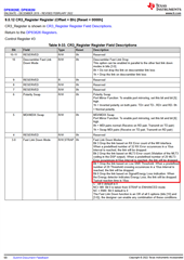
Specifically on the newer units with the DP83826, 0x0B (CR3 Register) on the management bus is set to 0x03.

Per the Datasheet here is the information for register 0x0B:

Fast Link Down Modes:
Bit 3 Drop the link based on RX Error count of the MII interface.
When a predefined number of 32 RX Error occurences in a 10us
interval is reached, the link will be dropped.

Bit 2 Drop the link based on MLT3 Error count (Violation of the MLT3
coding in the DSP output). When a predefined number of 20 MLT3
Error occurences in10us interval is reached, the link will be dropped.

Bit 1 Drop the link based on Low SNR Threshold. When a predefined
number of 20 Threshold crossing occurences in a 10us interval is
reached, the link will be dropped.

Bit 0 Drop the link based on Signal/Energy Loss indication. When
the Energy detector indicates Energy Loss, the link will be dropped.
Typical reaction time is 10us

C : Bit 0 default is 0

NC+ MII: Bit 0 is taken from STRAP in ENHANCED mode

NC + RMII: Bit 0 default is 0

The Fast Link Down function is an OR of all 5 options (bits [10] and
[3:0]), the designer can enable any combination of these conditions.

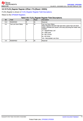
Also, 0x0F (Fast Link Down Status) was set to 0x03 on the system that was dropping link

Fast Link Down Status:
Status Registers that latch high each time a given Fast Link Down
mode is activated and causes a link drop (assuming the modes were
enabled)

1h = Signal/Energy Lost

2h = SNR Level

4h = MLT3 Errors

8h = RX Errors

10h = Descrambler Loss Sync

  • Here are datasheet snippets for additional context.

  • Hi Kevin,

    Apologies for the delayed response time. Below are my responses.

    1. The Registers you're looking for are not included in the datasheet, I'll get into contact with the Design team about registers that can get status without dropping link using FLD

    2. SNR threshold is an internal PHY threshold where PHY decides if Signal/Noise ratio if good enough to retain link when FLD is activated. I'll check with the team if there is an internal Register than can read the SNR value.

    3. Signal Detect Threshold is again, an electrical threshold for the PHY to decide on the validity of energy on-line. The exact value is not available.

    4. Yes, the link will be dropped if the threshold is crossed 20+ time within the 10us window.

  • Thanks - looking forward to further information from the design team.

  • Thank you for your patience, just a heads up this can take a week or so to get the required information.

  • I understand - thanks for the heads up.

  • Hi Alvaro - any details come around on this issue from engineering?

  • Hi Kevin,

    Alvaro is on PTO until next Monday. I am not involved in his conversations with the team. Let me trace out his conversations and respond to you by end of Thursday.

    --
    Regards,
    Gokul.

  • Hi Kevin,

    Sorry about the long wait time, the Design team has been working on it, along with several other inquiries. Apologies for the wait time.

    Regards, 

    Alvaro

  • Hi Kevin,

    Thank you for your patience and apologies for the extremely long wait on this one. I take responsibility for not communicating to the correct people initially.

    The response I received are below:

    1. Is there a PHY configuration permutation that enables us to actively monitor the Fast Link Down status flags (0x0F in management bus) but not have FLD automatically kill the link? This would be optimal for us. Or alternatively, do you only get access to the benefits of the flags in 0x0F when a link drop function is enabled/present?


       FLD always automatically kills the link; No way to only monitor the FLD flags


    1. Bit 1 of 0x0B references a signal to noise ratio detection mode that can trigger a FLD link drop. What is the actual SNR threshold that will trigger this flag? We would like to measure the performance of our old cable and the new cable we are designing to make sure it well exceeds the failure threshold of the this feature on the DP83826.


                    Defined in register 0x117[3:0]; Equation for obtaining threshold SNR = (-10*log10(Config_val/2^9)) - 3;


    1. Bit 0 of 0x0B references a signal/energy loss detection mode that can trigger a FLD link drop. This feature is extremely vague for me. How is it detecting signal/energy loss and what is the electrical criteria that it is testing for on the signal to consider the FLD signal/energy loss failure mode? I need to be able to capture this problem on the scope, and and understand what issue with the cable design that is causing it so I can address it.


            Energy threshold and window settings are present in register 0x128. If observed Energy in configured window is less than threshold value, Energy lost will trigger


    1. Does the "SNR level" bit flag in 0x0F get set to 1 for each occurrence of the SNR threshold crossing, or only set to 1 after 20 threshold crossings as described in the register description of 0x0B? When we were having the link drops, I want to understand if what we were seeing was 1 occurrence or 20+ occurrences of SNR threshold crossing.


                    It gets set if there is 20 threhold crossings as per register 0x104[5:0] in a period of 10us as defined in register location 0x116[4:0]. Same for all FLDs except for Energy lost based FLD which is triggered immediately on Energy loss.

    Regards,

    -Alvaro

  • This helps a lot to understand these features.  Does the energy threshold and window setting set by 0x128 use the same equation as SNR for 0x117[3:0]?  How can I correlate the energy threshold and window value to register 0x128?  This is a hidden register in the datasheet.

    Is 0x104[5:0] just a counter then for the threshold crossings?  This is also a hidden register.

    Register 0x116[4:0] is also not in the datasheet.  Is there any more detail on this register?

    Thanks,

    - Kevin.

  • Hi Kevin,

    Does the energy threshold and window setting set by 0x128 use the same equation as SNR for 0x117[3:0]?

    • Yes, SNR equation stays the same. We will not be able to share the details of internal registers 0x104 & 0x116.

    Regards,

    Alvaro