Part Number: TLIN1028-Q1
hello:
I want to use this IC to monitor power. but we have functional safety requirement.
for the following two items, i want to get detailed failure mode and clear description:
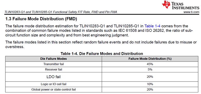
1. Logic or IO cell fail --- 10%
2. Global power or state control fail --- 20%
I want to get detailed failure mode to calculate FMEDA.
thank you so much!