This thread has been locked.

If you have a related question, please click the "Ask a related question" button in the top right corner. The newly created question will be automatically linked to this question.

DS90UB954-Q1: The change of Mipi channel leads to incomplete image

Part Number: DS90UB954-Q1
Other Parts Discussed in Thread: ALP
Imx8qm  mipi csi < ------> ds90ub954 <------> ds90ub953

                                                            <------->ds90ub953

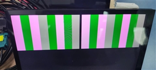
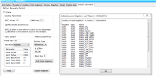
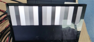
 when the configuration of ds90ub953 is in pattern mode and the configuration of the physical data channel of ds90ub954 is 4, the acquired image has black edges.

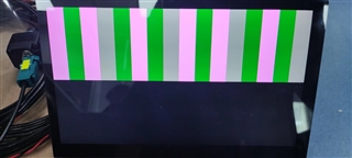
 When the physical data channel of ds90ub954 is 2, the display is normal

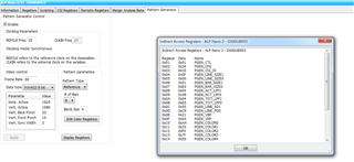
1.Register setting when Mipi physical data channel is 4

 {0x33, 0x43},   /* 4 lane */ 

 {0x1F, 0x00},   /* 1.6Gps csi clock per lane */ 

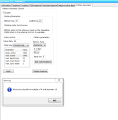
2. Register setting when Mipi physical data channel is 2

 {0x33, 0x63},   /* 2 lane */ 

 {0x1F, 0x00},   /* 1.6Gps csi clock per lane */ 

3.  The ds90ub953 maintains the following configuration:

{0x01, 0x07},
{0x02, 0x73},
{0x03, 0x5b},
{0x05, 0x0b},

{0xB0, 0x00},
{0xB1, 0x01},
{0xB2, 0x01},

{0xB1, 0x02},
{0xB2, 0x34},

{0xB1, 0x03},
{0xB2, 0x1E}, 

{0xB1, 0x04},
{0xB2, 0x0F},

{0xB1, 0x05},
{0xB2, 0x00},

{0xB1, 0x06},
{0xB2, 0x01},

{0xB1, 0x07},
{0xB2, 0xE0},

{0xB1, 0x08},
{0xB2, 0x04},

{0xB1, 0x09},
{0xB2, 0x38},

{0xB1, 0x0A},
{0xB2, 0x04},

{0xB1, 0x0B},
{0xB2, 0x65},

{0xB1, 0x0C},
{0xB2, 0x05},

{0xB1, 0x0D},
{0xB2, 0xC9},

{0xB1, 0x0E},
{0xB2, 0x21},

{0xB1, 0x0F},
{0xB2, 0x0A},

{0xB1, 0x10},
{0xB2, 0xAA},

{0xB1, 0x11},
{0xB2, 0x33},

{0xB1, 0x12},
{0xB2, 0xF0},

{0xB1, 0x13},
{0xB2, 0x7F},

{0xB1, 0x14},
{0xB2, 0x55},

{0xB1, 0x15},
{0xB2, 0xCC},

{0xB1, 0x16},
{0xB2, 0x0F},

{0xB1, 0x17},
{0xB2, 0x80},

{0xB1, 0x18},
{0xB2, 0x00},

{0xB1, 0x19},
{0xB2, 0x00},

{0xB1, 0x1A},
{0xB2, 0x00},

{0xB1, 0x1B},
{0xB2, 0x00},

{0xB1, 0x1C},
{0xB2, 0x00},

{0xB1, 0x1D},
{0xB2, 0x00},

{0xB1, 0x1E},
{0xB2, 0x00},

  • Hello,

    Just to confirm, register 0x33 of the 954 is the only change being made to both devices. Could you try updating the csi clock per lane value, for example setting register 0x1F = 0x02 for 800 Mbps.

    Regards,

    Darrah

  • Supplementary note:

    The format and size of the image generated by the pattern mode are consistent with the output of the camera. Therefore, the pattern mode is used for debugging.  In fact, the camera also encounters the problem of black edges。

    The connection mode between the camera and ds90ub953 is 4 data lanes

    reply:

    Premise of ignoring invalid data of image, the transmission rate of one ds90ub853 is: 1920(w)x1080(h)*60fps*16(YUV422-8bit)  /1024 / 1024= 1898 Mbps

    ds90ub954 connects 2 ds90ub953, total transmission rate of ds90ub954 is: 1898Mbps * 2 = 3796Mbps

    If ds90ub954 uses 4 data lanes, the transmission rate of each channel  is: 3796Mbps / 4 =  949Mbps

    If ds90ub954 uses 3 data lanes, the transmission rate of each channel  is: 3796Mbps / 3 =  1265Mbps

    If ds90ub954 uses 2 data lanes, the transmission rate of each channel  is: 3796Mbps / 2 =  1898Mbps

    Therefore, only data lanes 4 and 3 can be used in ds90ub954, and each data lanes needs to be set to 1.6Gbps。

    Using ds90ub954 with 2 data lanes is problematic,but it's strange that two lanes can work,so the conditions of  3 lanes and 4 lanes.

    1. Register setting when Mipi physical data lanes is 4

      {0x01, 0x02}, /* reset */
      {0xB3, 0x00}, /* Disabled BIST */
     /*TX port 0*/
     {0x33, 0x43}, /* 0x43 csi continuous clock mode, 4 lane enabled TX0, csi output enabled */
     {0x1F, 0x00}, /* 0x02(800Mbps) 0x00 1.6Gps csi clock per lane */
     {0x21, 0x01}, /* no replicate, Round robin forwarding*/
     {0x20, 0x00}, /* Forwarding enabled, RX0, RX1*/

    pattern mode:


    2. Register setting when Mipi physical data lanes is 3

      {0x01, 0x02}, /* reset */
      {0xB3, 0x00}, /* Disabled BIST */
     /*TX port 0*/
     {0x33, 0x53}, /* 0x53 csi continuous clock mode, 3 lane enabled TX0, csi output enabled */
     {0x1F, 0x00}, /* 0x02(800Mbps) 0x00 1.6Gps csi clock per lane */
     {0x21, 0x01}, /* no replicate, Round robin forwarding*/
     {0x20, 0x00}, /* Forwarding enabled, RX0, RX1*/

    3. the ds90ub953 configuration unchanged。

  • Hello,

    One note, you should include blanking (sync, back porch, front porch) when calculating rates instead of just the active pixels. Overhead should also be factored in (estimated as 25% if unknown) so the equation would be:

    totH x totV x framerate x 16 bits/pixel x 1.25 = transmission rate

    However using 4 lanes would still be supported with blanking/overhead included. 

    Since you are using YUV422 data type the block size should be set to 2. Can you update your block size from 4 to 2 inside pattern generator and see if that solves the issue?

    Regards,

    Darrah

  • Darrah:

    Thank you for your reply。

    I made a rough calculation to determine how many data channels are used and how many transmission rates are used. It is correct to multiply the coefficient of 1.25.The number of data channels and transmission rate used are consistent with the above analysis after multiplying the result by 1.25 coefficient.

    1. Block size setting error:

    2. Mandatory settings:

    {0xB1, 0x02},
    {0xB2, 0x32},

    Show black edges:

    3.  I guess that ds90ub954 has an error in YUV format conversion, so I tested the RGB format

         3.1 ds90ub953 Configure:


        {0xB0, 0x00},

        {0xB1, 0x01},
        {0xB2, 0x01},

        {0xB1, 0x02},
        {0xB2, 0x33},

        {0xB1, 0x03},
        {0xB2, 0x24}, //RGB888

        {0xB1, 0x04},
        {0xB2, 0x16},

        {0xB1, 0x05},
        {0xB2, 0x80},

        {0xB1, 0x06},
        {0xB2, 0x02},

        {0xB1, 0x07},
        {0xB2, 0xD0},

        {0xB1, 0x08},
        {0xB2, 0x04},

        {0xB1, 0x09},
        {0xB2, 0x38},

        {0xB1, 0x0A},
        {0xB2, 0x04},

       {0xB1, 0x0B},
       {0xB2, 0x65},

       {0xB1, 0x0C},
       {0xB2, 0x05},

       {0xB1, 0x0D},
       {0xB2, 0xC9},

       {0xB1, 0x0E},
       {0xB2, 0x21},

       {0xB1, 0x0F},
       {0xB2, 0x0A},

       {0xB1, 0x10},
       {0xB2, 0xAA},

       {0xB1, 0x11},
       {0xB2, 0x33},

       {0xB1, 0x12},
       {0xB2, 0xF0},

       {0xB1, 0x13},
       {0xB2, 0x7F},

       {0xB1, 0x14},
       {0xB2, 0x55},

       {0xB1, 0x15},
       {0xB2, 0xCC},

       {0xB1, 0x16},
       {0xB2, 0x0F},

       {0xB1, 0x17},
       {0xB2, 0x80},

       {0xB1, 0x18},
       {0xB2, 0x00},

       {0xB1, 0x19},
       {0xB2, 0x00},

       {0xB1, 0x1A},
       {0xB2, 0x00},

       {0xB1, 0x1B},
       {0xB2, 0x00},

       {0xB1, 0x1C},
       {0xB2, 0x00},

       {0xB1, 0x1D},
       {0xB2, 0x00},

       {0xB1, 0x1E},
       {0xB2, 0x00},

       3.2  ds90ub954 data lanes is 4, The display is normal without black edges

       {0x33, 0x43}, /* 0x43 csi continuous clock mode, 4 lane enabled TX0, csi output enabled */
       {0x1F, 0x00}, /* 0x02(800Mbps) 0x00 1.6Gps csi clock per lane */


      3.3 ds90ub954 data lanes is 3, The display is normal without black edges

      {0x33, 0x53}, /* 0x43 csi continuous clock mode, 4 lane enabled TX0, csi output enabled */
      {0x1F, 0x00}, /* 0x02(800Mbps) 0x00 1.6Gps csi clock per lane */


    4. From the test results, the rgb888 display is normal. Why is the YUV display abnormal?

    5. For the video of YUV422 1920x1080x60x1.25, if the two ds90ub953 inputs use 4 data lanes, can the ds90ub954 output use 3 data lanes ?

        The actual test video has the phenomenon of jamming, but there is no black edge

  • Hello,

    Could you provide a screenshot of the information tab in ALP? It is possible that the YUV error may be due to ALP and not the 953. Could you try to enable pat gen manually with the registers or scripting tab? The attached script below will enable pat gen for your parameters. You can also set the necessary registers by toggling the appropriate bits in the registers tab.

    #Patgen YUV 1920x1080p60  8 Colorbar
    devAddr = 0x30  #update as necessary
    
    Board.WriteI2C(devAddr,0xB0,0x00) # Indirect Pattern Gen Registers
    Board.WriteI2C(devAddr,0xB1,0x01) # PGEN_CTL - enable patgen
    Board.WriteI2C(devAddr,0xB2,0x01)
    Board.WriteI2C(devAddr,0xB1,0x02) # PGEN_CFG - blocksize 2
    Board.WriteI2C(devAddr,0xB2,0x32)
    Board.WriteI2C(devAddr,0xB1,0x03) # PGEN_CSI_DI
    Board.WriteI2C(devAddr,0xB2,1E) # YUV422
    Board.WriteI2C(devAddr,0xB1,0x04) # PGEN_LINE_SIZE1
    Board.WriteI2C(devAddr,0xB2,0x0F)
    Board.WriteI2C(devAddr,0xB1,0x05) # PGEN_LINE_SIZE0
    Board.WriteI2C(devAddr,0xB2,0x00)
    Board.WriteI2C(devAddr,0xB1,0x06) # PGEN_BAR_SIZE1
    Board.WriteI2C(devAddr,0xB2,0x01)
    Board.WriteI2C(devAddr,0xB1,0x07) # PGEN_BAR_SIZE0
    Board.WriteI2C(devAddr,0xB2,0xE0)
    Board.WriteI2C(devAddr,0xB1,0x08) # PGEN_ACT_LPF1
    Board.WriteI2C(devAddr,0xB2,0x04)
    Board.WriteI2C(devAddr,0xB1,0x09) # PGEN_ACT_LPF0
    Board.WriteI2C(devAddr,0xB2,0x38)
    Board.WriteI2C(devAddr,0xB1,0x0A) # PGEN_TOT_LPF1
    Board.WriteI2C(devAddr,0xB2,0x04)
    Board.WriteI2C(devAddr,0xB1,0x0B) # PGEN_TOT_LPF0
    Board.WriteI2C(devAddr,0xB2,0x65)
    Board.WriteI2C(devAddr,0xB1,0x0C) # PGEN_LINE_PD1
    Board.WriteI2C(devAddr,0xB2,0x05)
    Board.WriteI2C(devAddr,0xB1,0x0D) # PGEN_LINE_PD0
    Board.WriteI2C(devAddr,0xB2,0xC9)
    Board.WriteI2C(devAddr,0xB1,0x0E) # PGEN_VBP
    Board.WriteI2C(devAddr,0xB2,0x21)
    Board.WriteI2C(devAddr,0xB1,0x0F) # PGEN_VFP
    Board.WriteI2C(devAddr,0xB2,0x0A)


    Regards,

    Darrah

  • Hi,

    According to the above configuration, there are still black edges。What are the possible reasons for black edge?

    For Mipi signals using 4data lanes, why is the RGB format video normal, while the YUV format video has black edges

    {0xB0,0x00}, //Indirect Pattern Gen Registers
    {0xB1,0x01}, //PGEN_CTL - enable patgen
    {0xB2,0x01},
    {0xB1,0x02}, //PGEN_CFG - blocksize 2
    {0xB2,0x32},
    {0xB1,0x03}, //PGEN_CSI_DI
    {0xB2,0x1E}, //YUV422
    {0xB1,0x04}, //PGEN_LINE_SIZE1
    {0xB2,0x0F},
    {0xB1,0x05}, //PGEN_LINE_SIZE0
    {0xB2,0x00},
    {0xB1,0x06}, //PGEN_BAR_SIZE1
    {0xB2,0x01},
    {0xB1,0x07}, //PGEN_BAR_SIZE0
    {0xB2,0xE0},
    {0xB1,0x08}, //PGEN_ACT_LPF1
    {0xB2,0x04},
    {0xB1,0x09}, //PGEN_ACT_LPF0
    {0xB2,0x38},
    {0xB1,0x0A}, //PGEN_TOT_LPF1
    {0xB2,0x04},
    {0xB1,0x0B}, //PGEN_TOT_LPF0
    {0xB2,0x65},
    {0xB1,0x0C}, //PGEN_LINE_PD1
    {0xB2,0x05},
    {0xB1,0x0D}, //PGEN_LINE_PD0
    {0xB2,0xC9},
    {0xB1,0x0E}, //PGEN_VBP
    {0xB2,0x21},
    {0xB1,0x0F}, //PGEN_VFP
    {0xB2,0x0A},

  • The black edges are likely caused by a timing or blanking issue/mismatch. Can you confirm the active and blanking parameters of your display and provide a register dump and screenshot of the information tab after pat gen has been enabled?

    Regards,

    Darrah

  • Under the condition that the configuration of the  two-way 953 is unchanged, the display can be normal by using ds90ub960, and the acquisition and display problems of the imx8qm are eliminated. Also consult the FAE of NXP, and it is recommended to adjust the sampling timing of 954.
    Since the hardware design does not support ALP configuration, ALP is used to view the registers configuration.
    The following figure shows the configuration of registers of 954 and 953:

  • Okay, I did not realize that you were not enabling pat gen through ALP directly. Thank you for the register dumps, I will look over them to see if anything could be causing an issue and needs to be updated. 

  • Looking at the register values it looks like the 954 is reporting an unstable line length/count and CSI errors (register 0x4E). There are also length and data checksum errors (register 0x7A). These errors could indicate an issue with the connection. Additionally, could you try setting register 0x41 = 0xA9 on the 954?