This thread has been locked.

If you have a related question, please click the "Ask a related question" button in the top right corner. The newly created question will be automatically linked to this question.

SN65LV1224B: Unstable LOCK signal despite quality signals

Part Number: SN65LV1224B
Other Parts Discussed in Thread: SN65LV1023A

Hello,

I have been doing a lot of testing with the MAX9205/MAX9206 and SN65LV1023A/SN65LV1224B SerDes LVDS pairs. When testing with the Maxim Integrated chips I was successful in achieving a steady lock signal (over 10s of hours without the MAX9206 !LOCK signal going logic HIGH) with different TCLK/REFCLK frequencies of 16.666, 20, and 25 MHz. I have been using the MAX9205EVKIT evaluation boards for my testing. Recently, I swapped in the pin compatible SN65LV1023A and SN65LV1224B onto the MAX9205EVKIT. I was hoping to take advantage of the lower minimum PLL frequency of 10 MHz offered by TI SN65LV1224B. It seems like the PLL in the TI part might operate differently? There is no change to my test setup yet I am getting bit errors and the !LOCK signal is going logic HIGH even at the lowest frequency of 10 MHz. The !LOCK signal worsens as I increase the frequency to 11, 12 13 MHz etc. It is unusable at the 16.667 MHz frequency which I previously had great success with on the MAX9206.

Was I mistaken to assume these are pin compatible?

I am providing a clean TCLK and REFCLK. I am using 10 m of Cat5e. Both these variables were identical when testing the MAX9205/9206 pair. Attached are some oscilloscope images. One shows infintie persistence while triggering on the TCLK signal. You can see that the TCLK has very little jitter and that the phase relationship of the LVDS differential data is constant and also has very little jitter. The solid blue bar is demonstrating that the phase relationship between TCLK and REFCLK is not constant. They are on seperate PCBs which are not synchronized, but this is okay and I was able to successfully transmit data with the MAX9205/9206 pair with the same setup. I am surprised to see that the PLL on the SN65LV1224B doesn't remain locked to this serial data. The second image is triggering off the !LOCK signal going logic HIGH.

Thank you in advance for you time and advice. Kind regards,

  • Hi,

    Are you sending the SYNC pattern between SN65LV1023A and SN65LV1224B first?

    Thanks

    David

  • Hello David,

    Thank you for your reply. There are two scenarios:
    #1 The SN65LV1023A is continuously transmitting. The datasheet suggests that the deserializer lock will take longer than sending the SYNC patterns but the SN65LV1224B will eventually lock via random-lock synchronization to the serial data. After which it should remain locked, given the serial data it is receiving is of good quality. We performed numerous tests with the MAX9205 and MAX9206 pair where the !LOCK signal remained low after the initial PLL fix on the continuously transmitted serial data from the MAX9205.

    We are most interested in scenario #1 because we feel that if the !LOCK signal can remain low for a prolonged period of time when we are continuously transmitting data that would suggest better reliability and fewer bit errors. Scenario #2 below is how we are going to use these ICs, and if the !LOCK signal remains low just for the period of transmission that would be sufficient. However, the MAX9206 !LOCK signal remained low for nearly 60 hours when we ran a test over the weekend. We were simply surprised to see the SN65LV1224B !LOCK signal go logic HIGH only after minutes of receiving data.

    #2 Proper procedure. !PWRDN and DEN pulled to logic HIGH. Wait 2048*TCP (datasheet for SN65LV1023A suggests minimum 1026*TCP) for the Serializer PLL to stabalize. Pull SYNC2 to logic HIGH for longer than 6*TCP, but shorter than 1026*TCP, to send 1026*TCP of SYNC pattern, witness the !LOCK signal go logic LOW on the SN65LV1224B, request transmission of real data from SN65LV1023A, receive the data, turn off the serializer by pulling !PWRDN and DEN logic LOW.

    I hope this explanation helps. I am happy to provide any additional information. Thank you again for your help.

  • Hi,

    For scenario #2, are you still see the !LOCK signal go logic high after minutes of receiving data?

    With TCLK and REFCLK on two separate PCB, do you have a way to tie these two clocks to the same clock source and see if LV224B able to lock?

    Can you please capture REFCLK and RCLK and measure their respective frequency? 

    Thanks

    David

  • Thank you again David,

    "For scenario #2, are you still see the !LOCK signal go logic high after minutes of receiving data?"
    Our transmissions are very short, we send the SYNC pattern, wait the proper 1026 TCP and then transmit 65536 * 8-bit transmissions (choosing to not use 2 of the 10 available bits). This takes less than 10 ms and the !LOCK status stays low every time we "look" at it. When we do prolonged tests with repeated transmissions there are a small number of !LOCK status events that go HIGH.

    "With TCLK and REFCLK on two separate PCB, do you have a way to tie these two clocks to the same clock source and see if LV224B able to lock?"
    We have graduated past this since it is cheating to have the REFCLK = TCLK. When we did this in the past the !LOCK status was always stable and LOW like you would expect.

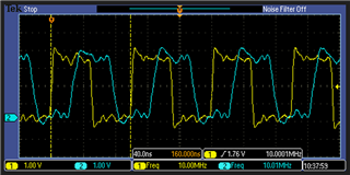
    "Can you please capture REFCLK and RCLK and measure their respective frequency?"


    Ch1 = REFCLK / Ch2 = RCLK

    They are both 10 MHz. When I take multiple single captures the relative phase changes but that is expected. I get identical results when measuring TCLK (on different board) and RCLK.

  • Hi,

    Do you have a frequency counter that you can use to measure the TCLK and REFCLK, we need to make sure they are within +/-100ppm.

    Thanks
    David