Part Number: SN65DSI83
Hi Team,
I am using SN65DSI83 MIPI to LVDS convertor connected to iMX8M Mini SoC in MIPI end and 10.1 inch Display in LVDS end.
It is functional in kernel 5.10 and I am developing Uboot driver for the same I took I2C dump form kernel and did the same register configuration in Uboot. There is a contradiction in PLL_EN and PLL_EN_STAT i.e., 0x0D and 0x0A register. PLL_EN value is 1 where as PLL_EN_STAT is 0
PFB Image:
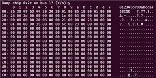
Kernel I2C dump:
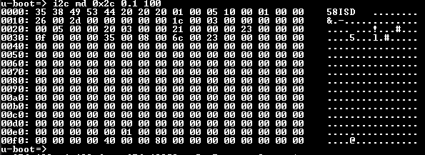
Uboot I2C dump:
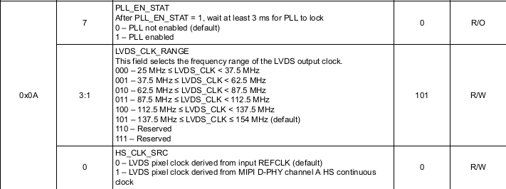
PLL_EN_STAT register description.
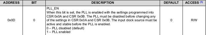
PLL_EN register description:
0x0D bit is 1 i.e., PLL is enabled but we can see from the PLL_EN_STAT it is not enabled.
I enabled the test pattern by writing 0x10 in 0x3c register. And I could see one vertical line at left side of display.
Could you please help us here to understand the issue while getting Test pattern in display.