This thread has been locked.

If you have a related question, please click the "Ask a related question" button in the top right corner. The newly created question will be automatically linked to this question.

DS90UB954-Q1: Link LOCK issue between UB954 and UB953

Part Number: DS90UB954-Q1
Other Parts Discussed in Thread: DS90UB935-Q1, DS90UB953-Q1, ALP

Hi,

I'm working on a image capturing function and the camera is based on the DS90UB953. I'm programming the soc PCBA which having a DS90UB954.

The link between is coax and fpdlink's on the port0 of 954. The POC is stable and confirmed from the oscilloscope.

The camera is from other company and is a black box to me.

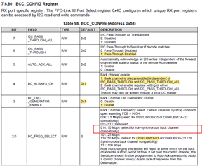
Now the problem is, the same camera can work with one of my project, PROJECT A, through BC_FREQ_SELECT configuration of 110: 50 Mbps (default for DS90UB953-Q1 or DS90UB935-Q1 CSI
Synchronous back channel compatibility).

Another project, PROJECT B, can only work through BC_FREQ_SELECT configuration of 010: 10 Mbps (select for non-synchronous back channel
compatibility). If I use the same 50M configuration, the link can not establish a stable lock status, and the LOCK_STS_CHG is always asserted.

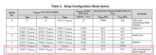
The default 954 MODE pin configuration of both my projects is,

I don't know if the camera is working under synchronous mode or non-synchronous mode, but it seems confusion from the behavior of the 2projects.

Can you help to analyze what's the situation between the 2projects from a serdes perspective? It's really confused me.

Thank you!

  • Hello,

    1. In PROJECT B, how are you changing the 954 from Sync Mode to Non-Sync Mode?
    2. Also, what PoC network are you using?
    3. Is there any way you can contact the manufacturer of the camera module and get more details on the serializer configuration?
    4. In PROJECT B, can you establish the connection using Non-Sync Mode and then run the MAP tool, in order to evaluate the quality of the channel link? And then post the results here?

    Best,

    Justin Phan

  • Hey Justin,

    Thank you for your fast reply.

    For the answer of your questions,

    1. I just configure 954's BC_FREQ_SELECT to 010: 10 Mbps (select for non-synchronous back channel compatibility).

    I'm not sure if this will change the 954 to non-synchronous or just reducing the back channel rate.

    2. The Poc Network on my board is copied from the TI spec and have some value changed. I've marked the changes below,

    3. Yes, I'm trying to get contact with them but still nothing from the tech team so far.

    4. For the MAP tool, I just downloaded it from TI website and I guess it need some kind of USB adapter I don't have for now.

  • Hello,

    1. Yes, changing the BC rate on the 954 is the correct way to set it to Non-Synchronous Mode.
    2. Okay, it seems that you are using the recommended 4G PoC network listed in the datasheet, which is rated to support Sync and Non-Sync operation between the 953 and 954.
    3. Okay, is the only change in hardware between PROJECT A and PROJECT B the camera module? Is the ECU board that holds the 954 deserializer the same?
    4. If you download ALP on a  lab computer, then you can communicate with the 954 chip by connecting the I2C pins to a USB2ANY adapter. Through this setup, you can run the ALP GUI on your computer and quickly debug using the built-in MAP tool. 
      1. An alternative is to adapt the MAP tool script and have it run on the existing processor in your system.
      2. If you download ALP and all the updates, then you can do into your computer directory to see the full MAP tool script:
      3. C:\Program Files (x86)\Texas Instruments\Analog LaunchPAD v1.57.0010\PreDefScripts\DS90UB954\ub954_margin_analysis_script

    Best,

    Justin Phan

  • Hey Justin,

    1. I'm wondering if changing the BC rate just means to changing the frequency, or also means changing between non-synchronous mode and synchronous mode?

    2. Got it.

    3. There's just one camera module. Project A and B are using the same one camera module. Project A and B are using different PCBA with similar schematic, just the power supply of A is 10V to the camera, but the B is like 9V. And for project B, I've soldered the coax cable to the PCBA, but on project A, there's a connector.

    4. Thank you Justin, I just found the python script, but need some time to figure out a way to port it to our system, since we are in a kind of debug mode.

    Thank you! 

  • Hello,

    1. When you want to pair a SER/DES in Synchronous MODE, you need to configure each device to have a matching setting. The deserializer needs to be set to output a specific Back Channel rate. The serializer will need to be set to use a specific signal as its reference clock, in order to drive the Forward Channel output. The deserializer only needs to be set to the correct Back Channel rate that is compatible with the serializer's current MODE.
    2. One thing to note is that the datasheet PoC network is only rated up to 150mA. Do you know if the camera PCB in PROJECT B is drawing more than 150mA?
    3. Since it seems there is some hand-soldering going on, there might be an impedance mismatch introduced by excess solder. We require a tightly-controlled 50-Ohms (+/-10%) single-ended impedance along the entire high-speed FPD-Link channel. Going outside this range will cause reflections that will distort the high-speed data and cause unstable LOCK.
    4. I would recommend starting with the script, to get a high-level overview of the channel link's quality.
      1. A deeper next step would be to confirm that the high-speed PCB traces meet the S-Parameters and Impedance requirements stated in the datasheet, through lab equipment measurements using a VNA.
      2. The 960 datasheet also includes the required channel specs for the entire channel, from DOUT+ on one PCB to RIN+ on the other:

    Best,

    Justin Phan

  • Hey Justin,

    The issue just got solved by using a standard coax cable without soldering.

    Thank you for your patience!