This thread has been locked.

If you have a related question, please click the "Ask a related question" button in the top right corner. The newly created question will be automatically linked to this question.

DS160PT801: Reference Clock Configurations and SSC

Part Number: DS160PT801
Other Parts Discussed in Thread: , USB2ANY

Hello Forum,

I am working on Re-timer topic for one of our requirement. I came across Reference clock configuration in the DS160PT801 datasheet.

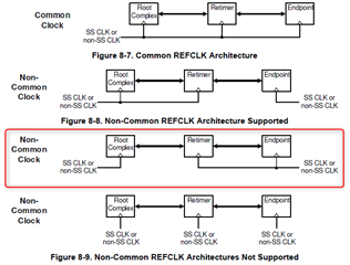
As mentioned in the datasheet , below marked separate reference clock connection is not supported.

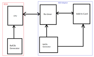
In my design, Re-timer is placed on the Adapter board( Re-timer + Add-in-module) as shown in below picture.

As we have no possibility to place the Re-timer at CPU and Adapter board connected to CPU Via 3m Cable. Planned to design Adapter board with Re-timer.

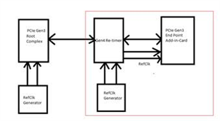
#1. Does this Re-timer suitable to my design requirement? What are the challenges If I connect the RefClk as shown in below picture?

#2 Do we need to configure RefClk generator to give SSC modulated clock to Re-timer (or) SSC modulation will happen in Re-timer, if we configure the Re-timer to enable SSC. Please correct my understanding on SSC configuration.

#3. Whether all the active components(RefClk Generator, Root Complex, Re-timer and Add-in-card Module) on the data-path are required to enable SSC?

#3. Any suggestions for RefCLk generators with 2 output ports.

#4. What is the Hardware Tool used to configure the Re-timer? Any recommendations for Flashing kits.

#5. Can I use Buffer Clock output from Re-timer and connect to Add-in-Card? as shown in below picture.

Thanks

Best Regards

Bharath Muthukuri

  • Hello Bharath,

    1. As you pointed out.  The datasheet says that this configuration is not supported.  

    2. The reference clock will generate a clock with SSC modulation.  Enabling SSC on the retimer tells the chip to expect a SSC clock at its inputs and lock onto the signal accordingly.

    3. Yes, all devices in the datapath should be able to support SSC if an SSC clock is used.  

    3. CDCE6214 is a good option for a PCIe reference clock.  They also have an Q100 version.

    4. We have software and documentation available through MySecure.  If you have access to the datasheet, you should have access to the software as well.  Let me know if you need access.  It's called SigCon Architect.  There are also EEPROM images stored on MySecure for various applications.

    5. Yes the reference clock output from the retimer can be used with the add-in card, but we should resolve this issue about the separate clock domains between the CPU and endpoint first. I am following-up with the systems engineer to check and see if there is anything that can be done.

    Regards,

    Nicholaus

  • Hi Bharath,

    I have send you a private message.  Let's continue this discussion about clock architectures offline.  If you have other questions unrelated to the clock, please continue to post on E2E.

    Regards,

    Nicholaus

  • Hi Nicholaus,

    Thank you for your reply.

    Find below few queries listed.

    #1. How is the understanding between Root Complex and Re-timer on clocking Configuration. Example: Re-timer first look for common clocking, if not found then shift to separate clocking. How is the clocking detection whether it is manual or auto detection?

    #2. In separate clocking, how to implement the ClkReq signal? How is the handshake between RC and Re-timer.

    #3. For down compatible speeds?How is the Speed configuration in Re-timer. Whether it is manual or Auto detectable?

    #4. What is the EEPROM size required? Any suggestion on Part?

    Thanks

    Bharath Muthukuri

  • Hi Bharath,

    1. The clocking detection for the retimer is not manual.  It must be switched to spread-spectrum clock tracking through EEPROM or SMBus communication.  Otherwise, it assumes common clocking.  The EEPROM images on MySecure include an SRIS example EEPROM.

    2. The CLKREQ# signal is simple in that a low value on this pin means the device is requesting a clock signal.  A high value means it is not, and the device will enter the L1.1 low-power state as described in the datasheet.  A similar question has been asked here: (+) SN75LVPE4410: PCIe CLKREQ Question - Interface forum - Interface - TI E2E support forums.  It includes an example topology from the PCIe specification.

    3. The retimer will automatically change to the highest datarate available that is advertised by the root complex and endpoint.  So, it is auto detectable.

    4. No EEPROM size required, but the MODE pin setting will change based on the EEPROM size as the datasheet says.  We used the AT24C16C-SSHM-B on our EVM.

    Regards,

    Nicholaus Malone

  • Hi Nicholaus,

    As mentioned in the datasheet, this part supports 2x4 link bifurcation. which means i can have two 1x4 slots. right?

    #1. So, can I still use x2 add-in-cards on 1x4 slot (or) will this be a limitation as this re-timer is not supporting 1x2 bifurcation with in the Die.

    #2. Using single Re-timer Is there any register setting, so that i can configure only 2 lanes with in the Die?

    #3. In DS160PT801X16EVM design MSP430 controller is used to convert USB to I2C. Can we use Market available USB to I2C convertor tool for Flashing. Do you have any suggestions for Flashing tool?

    #4. How SMbus hardware is enabled in the Re-timer? Does Re-timer comes with BIOS file loaded (or) do we need to load after BIOS file after first time power ON. If Yes, what is the tool used to load the BIOS file. Please correct my understanding.

    #5. Can we bypass the Re-timer to load the EEPROM? Or is it mandatory that we need to load EEPROM via Re-timer? Could you please provide EEPROM flashing tool details.

    Thanks

    Best Regards

    Bharath Muthukuri

  • Hi Bharath,

    1. This is a good question;  I don't believe I have seen this tested before, let me follow-up with my team and see if anyone has an answer.

    2. In general you shouldn't have to do much configuring besides what is in the example SRIS EEPROM on MySecure, but yes, there are channel-specific registers listed in the Programming Guide if you needed to use them.

    3. Yes you can, the flashing software would be specific to your USB-to-I2C converter.  The MSP430 controller on board is simulating our USB2ANY, which is available on ti.com: USB2ANY Evaluation board | TI.com.  If you use this with our Python API or SigCon Architect software for your custom board as well.

    4. The retimer does not have built-in memory, but it will load the register configuration from an attached EEPROM on powerup.  The EEPROM can be programmed directly, and then soldered onto the board, or it can be programmed on the board using the retimer.  We have an EEPROM programming tool in the SigCon Architect software and Python API, or you can refer to the EEPROM Programming Guide.

    5. The DS160PT801 does need some initial configuration.  It is generally recommended to use an EEPROM, but an alternative is to program the retimer before PCIe link training begins via the SMBus interface.  The EEPROM lines will need to be pulled high in either case using a pull-up resistor.  EEPROM flashing tools are available on MySecure per my answers in #4.

    Regards,

    Nicholaus