This thread has been locked.

If you have a related question, please click the "Ask a related question" button in the top right corner. The newly created question will be automatically linked to this question.

TUSB212: how to use electrical method besides eye diagram to see the AC/DC Boost setting difference

Part Number: TUSB212

Hello Ryan,

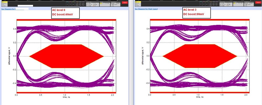
Could you kindly let us know how to see the significant difference between AC Boost and DC Boost on customer's case? Below are the eye diagram based on different AC/DC Boost value. May I know how can we tell apart for them? Any electrical test besides eye diagram could check to see the difference between different AC/DC Boost setting? Sorry to push but it is urgent case and I need to on-site support on 8/29 Taiwan time. Could you kindly check for me as soon as possible? Thanks a lot!

Best regards,

Ann Lien

  • Hi Ann,

    There are really no other ways to see a difference in signal after going through AC/DC Boost. The closest thing would be looking at the raw signal before and after it goes through the redriver.

    DC Boost is illustrated by the top and bottom levels of the eye diagram. These levels should be higher as the level of DC boost increases. AC boost is illustrated by the rising and falling edges of the signal that surround the eye mask. They should not be this wavy, however.

    As for these signals, the fact that the DC levels are not changing and that the AC edges look that way is odd. Have you had the customer look at the ENA_HS and CD pins already? If they have followed the testing procedure detailed in section 8.2.2.1 and have seen the proper waveforms on both these pins, then if you could have the customer send us the schematic they are using for this redriver, we can try to see if this issue is coming from their schematic.

    Please let me know if you have any other questions or concerns!

    Thanks,

    Ryan

  • Hello Ryan,

    I replied you via mail for customer's schematic. And I will double check with them if they've check ENA_HS and CD pin already. Thanks!

    Best regards,

    Ann Lien

  • Hi Ann,

    OK, sounds good. One thing I noticed is that the customer was a 22KOhm resistor on both Rdc1 and Rdc2 for DC Boost, though in the data sheet, it recommends at most one resistor to be placed at a time for DC Boost. I would ask the customer what level of DC Boost they intend to use, and then direct them to look at the datasheet to ensure they have the correct DC Boost level they want setup.

    Also, we recently added an App note for different test modes/procedures for testing our redrivers, it may be useful to show this to the customer to help ensure their ENA_HS and CD pins waveforms are correct. It should be listed under the TUSB21X redriver line pages as "TUSB21xx High-Speed Signal Quality Test Modes"

    Thanks,

    Ryan

  • Hello Ryan,

    It fixed with your recommendation, thanks a lot!!

    Best regards,

    Ann Lien