Because of the Thanksgiving holiday in the U.S., TI E2E™ design support forum responses may be delayed from November 25 through December 2. Thank you for your patience.

This thread has been locked.

If you have a related question, please click the "Ask a related question" button in the top right corner. The newly created question will be automatically linked to this question.

TRS213: The impedance status in TTL/CMOS output pins of TRS213

Part Number: TRS213
Other Parts Discussed in Thread: SN74LVC1G34

Hi Expert,

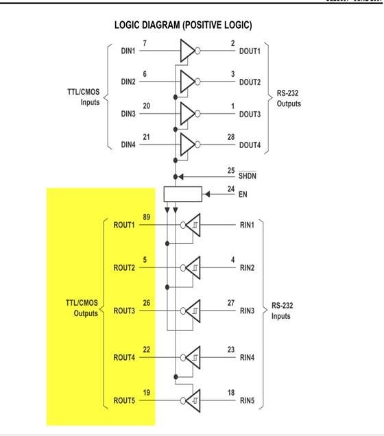
May I know when there is no power in TRS213IDBR, what is the impedance status of TTL/CMOS output pins?

Is it pull-down or Hi-Z?

Where can I get these information? datasheet or any applications note?
BR,

Aaron Chen

  • An unpowered output cannot actively drive a low level.

    The absolute maximum ratings forbid voltages larger than VCC + 0.3 V (there are clamping diodes to VCC).

  • HI Aaron,

    Its really neither - they are floating and they are bound by the following:

    There are 2 diodes on the ROUT pins - one from ground to pin and one from ROUT pin to VCC. If VCC is 0 and ground is 0 - the device is "high-Z" between -0.3V and 0.3V (there will still be leakage) - however if you exceed that the diodes are on and it won't really be hi-z anymore. When the power is off these pins should be around 0V but there is not drive causing it to be 0V - its floating. 

    Best,

    Parker Dodson

  • Hi Parker,

    Below is my customer's schematic.

    They would like to know the RS232 device resistance of pin 8.

    Since this is related to their EC control, the EC needs VIH which is higher than 2V.

    Due to the power sequence and the VIH of EC device.

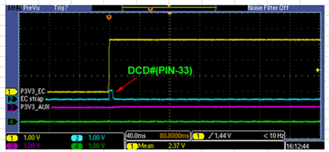
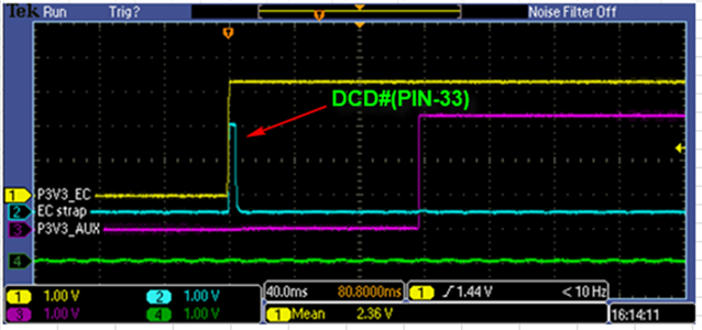
    If the R73 = 0ohm, the Pin 33 of EC is 0.6V.

    If the R73=100k ohm, the Pin 33 of EC is 2.6V.

    BR,

    Aaron Chen

  • The schematic is missing.

    The diode between ROUT1 and VCC has no specified resistance. A current will flow into ROUT1 and out of VCC, and this current is not limited. This current can damage the TRS213, and (partially) power up all devices connected to VCC.

    To prevent that current flow, insert a buffer that has a Hi-Z output when powered off, such as the SN74LVC1G34.

  • Hi Aaron,

    Clemens is correct there is no specified impedance - it is a diode connection. Using a buffer that is hi-z when powered off is a good idea to help block current flow into the pin.

    I would also suggest if you try the resistor method - it is more or less trial/error - 100K may not be the correct value but I don't have a great way to size it besides trying a few - the buffer is easier.

    Best,

    Parker Dodson

  • Hi Parker,

    Since the question is from end customer, my customer just want a comment from TI to know the detail of IC by Thursday.

    The end customer's question are below.

    1. What is the drive strength of the Transceiver and what is the required drive strength when using 100K?
    2. It is not so common to have Pull Down on Output of a driver, could you check with TI what is the reason for such strong P/D?

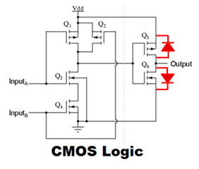
    Since the pin is TTL/CMOS outputs, that means is like below picture, and two diode of mosfet, am i making sense?

    Appreciate your support.

    Aaron Chen

  • Aaron,

    1. From my understanding the power is off n the application where power is going to the ROUT pin before its on- there is no drive strength when the driver is off. The current is being sunk into an ESD diode. The drive strength when the VCC is active isn't really spec'd beyond what is showed below:

    We don't have a max drive strength as the inputs are usually high impedance - we have a tested current and output voltage - which is the closest thing we have. 

    2. What you have in your schematic is not a PD/PU its a series current limiting resistor - and they are usually  < 500 Ohms in most applications. PD/PU resistors are used to ensure known logic levels are going to the controller at all times - its not an uncommon use case - it is used more often than not and required by certain protocols (including UART which many customers use RS-232 devices for UART). Its not required - but if the device is disabled ROUT is Hi-Z output so the bus could be floating which could cause issues at the controller end.

    3. The diagram doesn't include ESD diodes - which is what is sinking current when the power is off. 

    Best,

    Parker Dodson