This thread has been locked.

If you have a related question, please click the "Ask a related question" button in the top right corner. The newly created question will be automatically linked to this question.

DS90UB935-Q1: Question about DS90UB935-Q1 and DS90UB954-Q1

Part Number: DS90UB935-Q1
Other Parts Discussed in Thread: DS90UB954-Q1, , ALP

I have a project using DS90UB935-Q1 and DS90UB954-Q1。

The sensor use the 2 lane mipi-csi.

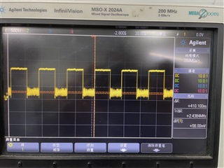
There is a MIPI signal measured by the oscilloscope on the TX side, but there is no signal on the RX side。

And  I can't read the I2C address of the TX, only the I2C address of the RX.

Can you provide relevant parameter configurations to make the sensor work,Please help!!!Thanks!

  • Hello,

    Can you clarify what you mean by TX and RX?

    Are you referring to the serializer as TX and the deserializer as RX? If so, is your processor located on the local I2C bus of the deserializer?

    Best,

    Justin Phan

  • You are right。My processor located on the local I2C bus of the deserializer,and I can read deserializer's address and modify its parameters via the I2C bus.

  • Okay, so it seems that you have probed the CSI-2 pins leading from the Camera Sensor to the input port of the 935 serializer and see a signal, but when you probe the CSI-2 output pins on the 954, you are not getting the correct CSI-2 signals. Is my understanding correct?

    1. What MODE settings are the paired 935 and 954 set to?
    2. Can you check to see if the 954 detects a stable LOCK?
      1. First, make sure the RX_READ_PORT register bit in register 0x4C in the 954 is set to the RX Port that is connected to the serializer.
      2. Next, read register 0x4D multiple times.
      3. After multiple reads, LOCK_STS should remain b'1 and the LOCK_STS_CHG should remain b'0.

    Best,

    Justin Phan

  • Hello, as you said, I can measure the MIPI signal waveform before 935 and it is correct.
    FAE gave me some parameter configurations, but since I'm not in the company now, I don't remember the specific parameter configurations. I need to look it up to answer you.
    At present, the LOCK pin of 954 is high level.
    The address of 935 (0X30) can also be accessed now. After configuring 935 CSI_LANE_SEL to 0x1, a relatively correct MIPI data signal can be measured at the 954 end. But MIPI's clock signal doesn't look right, it looks a bit like the data signal.
    I have used 933 and 934 chips in the past, which can be used normally without I2C configuration. So I don't know how to configure the parameters of 935 and 954.Can you give me a complete parameter to configure 935 and 954.
    See if it can output the waveform correctly.
    Thank you so much!

  • If both the SER/DES are powered-up in the same MODE, then all you need to do is enable each RX Port to forward the received video data to the CSI-2 TX Port on the 954.

    Can you clarify what MODE each device is set to?

    After making sure the MODE pins match, make sure to verify that the 954 is LOCKing to the serial stream sent by the serializer, using the steps I listed above. If you get a stable LOCK, then you need to enable forwarding on the active RX Port on the 954 deserializer and also enable the TX Port on the 954 deserializer.

    See Section 7.4.28 CSI-2 Forwarding in the 954 datasheet for how to output video data that the 954 receives from its connected serializer.

    Best,

    Justin Phan

  • Both 935 and 954 modes are CSI-2 Synchronous mode.
    The I2C configuration of the 954 is as follows:

    WriteI2C(0x4c,0x01)

    WriteI2C(0x72,0xe8)

    WriteI2C(0x6d,0x7c)

    WriteI2C(0x20,0x00)

    WriteI2C(0x33,0x23)

    WriteI2C(0x58,0x9e)
    The configuration of the 935 is as follows:

    WriteI2C(0x02,0x53)
    The rest use the default configuration.
    After the configuration is complete, the waveform of MIPI CLK can now be measured, but the waveform of MIPI DATA does not look right. Figure 1 is the input MIPI DATA waveform of the 935 terminal. Figure 2 is the output MIPI DATA waveform of the 954 terminal.
    After the SOC receives these MIPI signals, it cannot output images.

    Figure 1

    Figure 1

    Figure 2

  • WriteI2C(0x20,0x00)

    In your application, are you connecting two 935 serializers to each RX Port on the 954? The line above is enables both RX Port 0 and RX Port 1 on the deserializer, which is only used if you have two serializer connected to the 954.

    And is the portion of the signal that you are zoomed-in on the High-Speed Data portion of the video transmission?

    Are you able to enable PATGEN on the 954, to see if a similarly distorted video is being outputted on the 954 CSI-2 transmitter?

     This can be done by connecting a lab computer to the I2C bus on your PCB and running ALP, or by setting a series of registers on the 954. Below is an example script that configures the 954 to output 1280x720 video in 30fps and RAW12:

    """
      Copyright 2018 Texas Instruments Incorporated. All rights reserved.
    
      IMPORTANT: Your use of this Software is limited to those specific rights
      granted under the terms of a software license agreement between the user who
      downloaded the software, his/her employer (which must be your employer) and
      Texas Instruments Incorporated (the "License"). You may not use this Software
      unless you agree to abide by the terms of the License. The License limits your
      use, and you acknowledge, that the Software may not be modified, copied or
      distributed unless embedded on a Texas Instruments microcontroller which is
      integrated into your product. Other than for the foregoing purpose, you may
      not use, reproduce, copy, prepare derivative works of, modify, distribute,
      perform, display or sell this Software and/or its documentation for any
      purpose.
    
      YOU FURTHER ACKNOWLEDGE AND AGREE THAT THE SOFTWARE AND DOCUMENTATION ARE
      PROVIDED AS IS WITHOUT WARRANTY OF ANY KIND, EITHER EXPRESS OR IMPLIED,
      INCLUDING WITHOUT LIMITATION, ANY WARRANTY OF MERCHANTABILITY, TITLE,
      NON-INFRINGEMENT AND FITNESS FOR A PARTICULAR PURPOSE. IN NO EVENT SHALL TEXAS
      INSTRUMENTS OR ITS LICENSORS BE LIABLE OR OBLIGATED UNDER CONTRACT,
      NEGLIGENCE, STRICT LIABILITY, CONTRIBUTION, BREACH OF WARRANTY, OR OTHER LEGAL
      EQUITABLE THEORY ANY DIRECT OR INDIRECT DAMAGES OR EXPENSES INCLUDING BUT NOT
      LIMITED TO ANY INCIDENTAL, SPECIAL, INDIRECT, PUNITIVE OR CONSEQUENTIAL
      DAMAGES, LOST PROFITS OR LOST DATA, COST OF PROCUREMENT OF SUBSTITUTE GOODS,
      TECHNOLOGY, SERVICES, OR ANY CLAIMS BY THIRD PARTIES (INCLUDING BUT NOT
      LIMITED TO ANY DEFENSE THEREOF), OR OTHER SIMILAR COSTS.
    
      Should you have any questions regarding your right to use this Software,
      contact Texas Instruments Incorporated at www.TI.com.
    
    """
    # CSI patgen                 
    # Python script CSI_patgen_RAW12_1280x720p30
    # Version 0.91                
    
    # CSI cont clk and CSI enable                           
    # board.WriteReg(0x32, 0x01)                            
    board.WriteReg(0x33, 0x03)                 
       
    board.WriteReg(0xB0, 0x02)                # IA_AUTO_INC=1
    board.WriteReg(0xB1, 0x01)                # PGEN_CTL
      
    board.WriteReg(0xB2, 0x01)                # PGEN_ENABLE=1
    board.WriteReg(0xB2, 0x33)                # PGEN_CFG
    board.WriteReg(0xB2, 0x2C)                # PGEN_CSI_DI
    board.WriteReg(0xB2, 0x07)                # PGEN_LINE_SIZE1
    board.WriteReg(0xB2, 0x80)                # PGEN_LINE_SIZE0
    board.WriteReg(0xB2, 0x00)                # PGEN_BAR_SIZE1
    board.WriteReg(0xB2, 0xF0)                # PGEN_BAR_SIZE0
    board.WriteReg(0xB2, 0x02)                # PGEN_ACT_LPF1
    board.WriteReg(0xB2, 0xD0)                # PGEN_ACT_LPF0
    board.WriteReg(0xB2, 0x03)                # PGEN_TOT_LPF1
    board.WriteReg(0xB2, 0x20)                # PGEN_TOT_LPF0
    board.WriteReg(0xB2, 0x10)                # PGEN_LINE_PD1
    board.WriteReg(0xB2, 0x47)                # PGEN_LINE_PD0
    board.WriteReg(0xB2, 0x0A)                # PGEN_VBP
    board.WriteReg(0xB2, 0x0A)                # PGEN_VFP
    board.WriteReg(0xB2, 0xAA)                # PGEN_COLOR0
    board.WriteReg(0xB2, 0x33)                # PGEN_COLOR1
    board.WriteReg(0xB2, 0xF0)                # PGEN_COLOR2
    board.WriteReg(0xB2, 0x7F)                # PGEN_COLOR3
    board.WriteReg(0xB2, 0x55)                # PGEN_COLOR4
    board.WriteReg(0xB2, 0xCC)                # PGEN_COLOR5
    board.WriteReg(0xB2, 0x0F)                # PGEN_COLOR6
    board.WriteReg(0xB2, 0x80)                # PGEN_COLOR7
    board.WriteReg(0xB2, 0x00)                # PGEN_COLOR8
    board.WriteReg(0xB2, 0x00)                # PGEN_COLOR9
    board.WriteReg(0xB2, 0x00)                # PGEN_COLOR10
    board.WriteReg(0xB2, 0x00)                # PGEN_COLOR11
    board.WriteReg(0xB2, 0x00)                # PGEN_COLOR12
    board.WriteReg(0xB2, 0x00)                # PGEN_COLOR13
    board.WriteReg(0xB2, 0x00)                # PGEN_COLOR14
    board.WriteReg(0xB2, 0x00)                # Reserved

    Can you also provide a register dump of the 954 registers, so that I can try to see if there are any status errors or flags that stand out?

    Are you also able to provide a schematic that shows the connections being made to the 954 chip, so that I can review?

    This is a public forum, so if you are unable to share publicly, we can share the information over private message.

    Best,

    Justin Phan

  • Thank you very much for the RAW 12 PATGEN you provided. By configuring PATGEN for 954, I found that there is a problem with the back-end decoder board. After replacing the back-end decoder board, the image output is normal. In addition, I tested the 0x20 register, and writing 0x00 or 0x20 has the same effect.

  • Thank you for posting an update. It seems the issue has been resolved. In that case, I will close this E2E thread.