This thread has been locked.

If you have a related question, please click the "Ask a related question" button in the top right corner. The newly created question will be automatically linked to this question.

DS125DF410: Link up and down issue of DS125DF410SQ

Part Number: DS125DF410

Hi, this is Minkyu Cho in SECUI.

I already uploaded the case at https://support.ti.com/csm/?sys_id=1972996e47e1d5145c930541e36d433f&id=csm_ticket&table=sn_customerservice_case

But I will tell you the phenomenon of this issue.

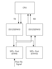
As you can see the attached file, ETH9 and ETH10 is link up.

In this case only, ETH9 link up and down is happened.

When the only ETH9 is link up, link up and down is not happend. (ETH9 has a poor RX signal)

I set the register 0x1C from default value 24 (4MHz) to 90 (9MHz).

And write the register 0x40 to 0x0A follow as programming guide.

After above register setting, link up and down is not happend.

So, I want to know what is the CDR bandwidth and Charge pump.

And I want to know the this register's function and operation.

Thank you.

  • Hi Minkyu,

    Unfortunately I do not have access to that support case.  Please feel free to send relevant files over E2E direct message.

    My understanding of what you have described is that under typical operation, ETH9 intermittently loses link.  Is this correct?  Are there any external variables that impact this?


    To help us better understand this issue, could you share a register dump?  If it's possible to get a register dump while the link is down, this might be helpful as well.

    The CDR bandwidth impacts how much jitter the CDR system can track.  A larger CDR bandwidth enables the CDR system to better track jitter, but consequently it passes more jitter to the output. The following presentation includes some details about CDR bandwidth.

    What is clock and data recovery? | TI.com Video

    Thanks,
    Drew

  • ETH9 has poor RX signal I measured the optic eye diagram.
    Please confirm the below 2 cases.

    Case 1 : When the only eth9 is linked up, link up/down is not happened.

    Case 2 : When eth9 and eth10 is linked up, eth9 link up/down is happened periodly.

    I don't know why only if CASE 2, link up/down is happend.
    And when I set the below register why this issue has gone?
    Could you let me know the reason ?
    ------------------------------------------------------------------------------------------------------------
    I set the register 0x1C from default value 24 (4MHz) to 90 (9MHz).
    And write the register 0x40 at 0x0A follow as programming guide.
    ------------------------------------------------------------------------------------------------------------

    And I can't get the register dump because that is a site issue.

  • Hi,

    Could you let me know the reason ?

    It is possible that crosstalk may be introducing jitter that can be better tolerated by increasing the CDR bandwidth.

    Can you provide any characteristics of the ETH9 RX signal such as an eye diagram or jitter measurements?

    Are you able to provide HEO/VEO measurements from the retimer with ETH9 linked up and with ETH9 and ETH10 linked up?  It would be helpful to compare these two cases so that we can see if ETH10 is impacting the eye on ETH9.

    Thanks,
    Drew

  • Thanks for your quick response.

    You mean input jitter can be ignore by CDR bandwidth increasing. Is it right ?

    Attached file is optical eye diagram. Please confirm the waveform.
    And as I told you, system is in the site. So I can't compare the HEO/VEO.

  • I can't upload the eye diagram. Drag and drop or Insert has not operate. 

  • Hi,

    And as I told you, system is in the site. So I can't compare the HEO/VEO.

    I'm confused by your setup.  How were you able to configure CDR bandwidth if you're not able to communicate over I2C?

    You mean input jitter can be ignore by CDR bandwidth increasing. Is it right ?

    By increasing CDR bandwidth, the retimer is able to tolerate more input jitter before it loses CDR lock.  This comes at the cost of passing more jitter to the retimed signal.

    I can't upload the eye diagram. Drag and drop or Insert has not operate. 

    If drap/drop is not working, try to copy/paste the image from your clipboard into the response.  This typically works.

    Thanks,

    Drew

  • I'm confused by your setup.  How were you able to configure CDR bandwidth if you're not able to communicate over I2C?

    => I'm sorry for confusing you. For a 1 day only I could set the register at the site.  After then I can't modify or read the system becasue the site is operating.

    By increasing CDR bandwidth, the retimer is able to tolerate more input jitter before it loses CDR lock.  This comes at the cost of passing more jitter to the retimed signal.

    => Thanks you. I understood the CDR bandwidth's function.

    If drap/drop is not working, try to copy/paste the image from your clipboard into the response.  This typically works.

    => Copy and Paste is stiil not working.

    Thank you.

  • Hi,

    I'm sorry for confusing you. For a 1 day only I could set the register at the site.  After then I can't modify or read the system becasue the site is operating.

    Thanks for the clarification, I understand now.  Do you anticipate that you'll be able to do on site debug in the future?

    Copy and Paste is stiil not working.

    I will DM you my email so that you can share this.

    Thanks,

    Drew

  • I sent you the image file please check the attached file.

    I'm not done with the site issue yet, so it looks like I need to debug the site issue.

    In the case 2, will you guess the reason of phenomenon except for compare the HEO/VEO each port ?
    Do you think only crosstalk is reason of this issue ?

  • Hi Minkyu,

    Thank you for sharing the image.  Our retimer channels operate independently of one another.  If the issue is dependent on multiple inputs, then I think we have to consider what aspects of the system would behave differently with multiple inputs present when compared to just one input.

    The factors that come to my mind are:

    • Crosstalk
    • Power rail stability
    • Any other parts of the signal chain within the system

    If you are able to go on site, getting a full register dump might be helpful in addition to HEO/VEO values.  It would also be interesting to see if your CDR bandwidth modification impacts the HEO/VEO values that you measure.

    Also, can you confirm which adapt mode you are operating in?  Is DFE enabled?

    Thanks,
    Drew