This thread has been locked.

If you have a related question, please click the "Ask a related question" button in the top right corner. The newly created question will be automatically linked to this question.

DS160PR410: How to disable PCI Express RX detection state machine via I2C bus in slave mode?

Part Number: DS160PR410

I need to disable the RX detection state machine via an I2C bus from an external controller and always enable 50-ohm termination. I tried to set bit 6 in register 0x0D - Manual override of rx_detect_p/n decision to always return valid. But the register 0x01 showed that the rx is not detected. I tried to reset the rx detection state machine by setting and resetting bit 3 in register 0x0D, but it did not help. I tried to set bit 5 in register 0x06 and it helped. The register 0x01 showed that both pins detected the receiver termination. My question is if I enable overrides for driver and equalizer enables by setting bit 5 in register 0x06, how to set up other bits to enable normal operation? I only need to disable the rx detection. The CTLE index may change during operation from 0 to 15. Do I need to enable CTLE Termination bit 6 in register 0x04, Enable CTLE bit 3 in register 0x04, Enable Pre-driver bit 4 in register 0x06, Enable Driver bit 3 in register 0x06 and Enable CM Loop bit 2 in register 0x06? What is the CM loop?

  • Greetings,

    Reg 0x06[5] is the override for the driver and CTLE settings. If you are planning to control device through register then we must first set this bit. 

    For normal operation, please note Reset column in the programming guide. As long as these settings meet your requirement you do not need to make a change. Otherwise you can change CTLE settings or driver gain settings since you already have reg 0x06[5] enabled. Also, since you are using register control without RX detect functionality, you should turn on Reg 0x04[6] and 0x04[3]. Reg 0x06[3] should be turned on as well. Pre-driver could be turned on depending on the signal conditioning or eye opening that you may need at the output of the device. 

    To help with detailed register settings, you can install GUI for the DS160PR410 device. Then there is macros for setting different EQ boost and other function. You can check these macros to give you a closer look at different register settings. After you install this GUI, here is the path for checking these macros:

    Additionally you can use low level control setting in this GUI to setup RX detect functionality and etc on your own board.

    Regards,,Nasser

  • Hi Nasser,

    Thank you for your response. Could you please answer the following questions:

    1. What is the indication that the rx detection is disabled and 50ohm termination is always enabled? Is it the status of bits 6 and 7 in reg 0x01?
    2. What the pre-driver does and when should it be enabled or disabled?
    3. What is the CM Loop – bit 2 in reg 0x06, and how to set it?

    I have SigCon Architect EVM GUI v3, but it cannot be connected to our board. We can read and write registers from our controller, so we just need to know the settings. The SigCon low-level control is not useful because it just shows the bit settings. It does not show how to disable the rx state machine. I could not find a macro that enables or disables the rx termination. We can change equalization settings from the controller. Our system works well with some endpoints and does not with others. We think that the problem is with the rx terminations in the DS160PR410. We have a similar system with the DS160PR410, but the configuration is done by strap pins. Now we need to switch to the I2C configuration.   

    Thanks,

    Igor

  • Hi Igor,

    1). Reg 0x01[7:6] are mainly used for PCIe RX detect status. Suggestion is to put the device in 50-ohm non-PCIe mode forcing pin RX_DET pin 26 in L3 mode. This would enable termination both on the output and the input of the channel. RX detect pin setting has priority over register settings. You should observe increased current consumption once this goes into effect. 

    2). Internal to the part, there are two drivers on the output of the device. These bits - reg 0x06[4:3] refer to these two blocks.

    3). CM Loop refers to the Common Mode loop circuit. This loop maintains constant common mode voltage at the output driver.

    Regards,Nasser

  • Hi Nasser,

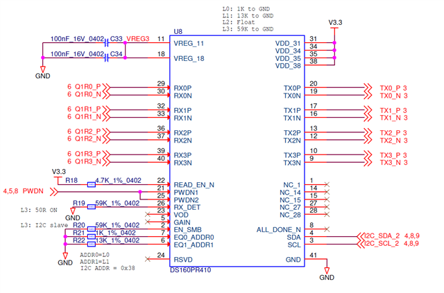
    1. We have a 59K resitor on pin 26 RX_DET - see schematic below. But Reg 0x01[7:6]="00" without additional configuration. 


    It might be difficult to check power consumption by soldering and desoldering the resitor. 

    In the manual mode (reg 0x06[5]=1), the Reg 0x01[7:6] shows "11".  

    2. We tested with the following settings: reg 0x04=0x5F, reg 0x06=0xFC. With these settings, reg 0x01[7:6}="11" and does not depend on bits 6 and 3 in reg 0x0D.

    3. Should we set reg 0x06[4:3]="11"? What is the purpose of the pre-driver?

    Thanks,

    Igor 

  • Hi Igor,

    1). With RX_DET pin 26 at L3, this disables PCIe RX detection process. Reg 0x01[7:6] are mainly used for PCIe RX detect status monitoring not for non-PCIe applications. Please note by forcing pin 26 to L3, we have input and output termination. Otherwise this means we have a device/pin malfunction. Please just make sure you have L3 mode and you can be assured 100% that there is termination - otherwise device is faulty. 

    2). Please note #1 above.

    3). Sure please go ahead and set these. These enable the output drivers. Note reg 0x06[5] need to be on as well for these to go into effect. We need to set reg 0x06[4:3]= "11" because normally PCIe RX detect state machine would turn these bits on internally AFTER it has detected a termination. But here you are manually controlling termination through pin 26. In this case, you are in manual termination mode versus PCIe mode.

    Please note if you turn on non-PCIe 50-ohm termination, you may have interoperability issues with some end point. Please check this with multiple end points.

    Regards,Nasser 

  • Thanks, Nasser. Our application is a non-standart PCIe.