This thread has been locked.

If you have a related question, please click the "Ask a related question" button in the top right corner. The newly created question will be automatically linked to this question.

TCAN4550: BRSE Bit : Write Protected

Part Number: TCAN4550

Hi,

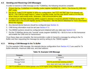
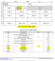
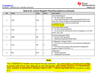
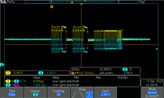
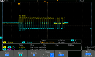
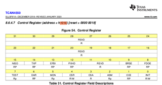
I am testing CANFD. Sending 64 data bytes at regular speed is blocking the CAN bus. I want to turn on bit rate switching by writing 9th bit of the register h1018. But 9th bit is READ WRITE PROTECTED type. So I am not able to write this bit to high for enabling bit rate switching for transmission enabled. What is the solution for this?

Below is the snapshot for the same.

Regards,

Akshay

  • Hi Akshay,

    The procedure for setting the BRS bit is outlined in the TCAN455x Software User's Guide and if you haven't read through this, it is a good resource to review.  The images I'm sharing in this post come from this document.

    But basically you can only change the "write protected" configuration bits when the device is in the "Initialization (INIT) Mode" which occurs when the INIT bit of the Control register (0x1018) is set to 1.  You also need to set the Configuration Change Enable (CCE) bit to 1 to allow these bits to be set.  However, in order for it to be set, the INIT bit has to already be set to 1.  Therefore if you need to set both the CCE and INIT bits to 1, this may take multiple writes to the Control register to allow the INIT bit to get set to 1, and then a second write will let the CCE bit to get set to 1.  Then once the CCE bit is set to 1, all write protected bits can be set including the BRSE and FDOE (FD Operation Enable) bits.  The FDOE bit also needs to be set to allow CAN FD mode in order for the bit rate switch to occur.

    Just setting the FDOE and BRSE bits in the Control Register will not necessarily cause all CAN FD messages to be transmitted in the FD format with Bit rate switch.  These bits just allow messages in that format to be transmitted.

    The FDF and BRS bits in the TX FIFO/Buffer Element header will also need to be set to 1 in order for that message to be transmitted in FD format with Bit rate switch.

    Regards,

    Jonathan

  • Hi Jonathan,

    Once CSR Bit is set the device turns to standby mode. But according to the instruction it has to be cleared but when I try to clear the CSR bit, It is not happening. As per the instruction from the user guide it has to be cleared. Could you please let us know what has to be done?

    Regards,

    Akshay 

  • Hi Akshay,

    The CSR bit should not be written to the device through SPI and issuing a Clock Stop Request is used to prepare the device for Power Down or Sleep Mode.  This stops the clock and will disrupt the normal operation of the device.  The datasheet notes that the CSR bit must always have a '0' written to this bit when doing a SPI Write to set other bits.

    The solution is to not set this bit to '1' and allow the device to internally handle this internally.  The MCU application code should not need to ever set this bit and a '0' should always be written to this bit.  The note is to inform the user that the Read-back value will be a '1' and therefore a normal Read-Write-Modify function will need a special capability to ensure that a '0' is always written to this bit.

    Resetting or power cycling the device would likely be required to recover from a situation where this bit was set by the MCU.

    The TCAN4550 uses the "M_CAN" CAN FD Controller IP developed by Bosch.  Additional information about the CAN FD controller and register settings can be found in M_CAN User's Manual on Bosch's website. 

    The register addresses are the same with the one exception that an offset of 0x1000 is added to each address in the TCAN4550.  Therefore the MCAN address of the Control Register 0x18 is the same as the TCAN4550 address of 0x1018.

    Regards,

    Jonathan

  • Hi,

    Below are few of our observation:

    1) Test Configuration & Issue Observed:

    • 2TCU's are connected to the PCAN. PCAN is the transmitter and one of the TCU1 is receiving the data which is sent by PCAN tool. In TCU2 the CANFD is not initialized.
    • When PCAN tool is transmitting the data frame with BRS bit enabled, the TCU1 is receiving the CANFD frame. But in this condition when we initialize the CANFD in TCU2 the error frames are getting generated and it is observed in the PCAN tool.
    • But if we perform the same above scenario with BRS bit disabled in the PCAN tool, then we are not observing the error frames in the PCAN tool.
    • Snapshot taken from CRO of error frame with BRS bit is given below:

    • Snapshot taken from CRO without BRS bit is given below:

    2) Queries:

    • After insmod & before iplink, in which state the TCAN comes up? Is it in standby mode or normal mode?
    • What is the reason for error frame with BRS setting? Is it driver issue?
    • Is the error frames generated from the driver?

    3) Possible Solution:

    • We had asked another query in the forum regarding the driver and we are waiting for the fix of that driver. When can we get the driver fix from the 3rd party? The query is for your the reference (TCAN4550: Error Code generated during insmod of tcan module).
    • In the meatime, is there anything that can be done on the driver side, so that we can take a look on to that from our side.

    Regards,

    Akshay

  • Hi Akshay,

    1.) All notes on the bus should have the same settings and features enabled.  If a CAN FD frame is transmitted on the bus, ALL nodes must have FD enabled, otherwise the node that does not have FD enabled will throw and Error Frame on the message. 

    Likewise, if the FD message is transmitted with a faster Data rate, ALL nodes must have the BRSE, or equivalent Bit Rate Switch setting enabled and must have the same Data Bit Timing settings.  Otherwise, the node that does not have the BRSE enabled or has different Data Bit Timing settings will throw an error frame on the message. 

    Because error frames are generated when you have nodes trying to communicate with different configurations shows the system is working as intended during this test based on the CAN FD protocol and standards.

    2.) Based on the question I'm assuming you are referring to the TCAN4x5x Linux Driver.  This is a device support forum and I am not sure exactly when the driver transitions the TCAN4550 device from Standby Mode to Normal Mode.  However, the TCAN4550 always powers up into Standby Mode.  It will only transition to Normal Mode from Standby Mode when the processor sets the MODE_SEL bits in the Modes of Operation and Pin Configuration Register 0x0800[7:6] to Normal Mode (2'b10).

    The BRS error is due to not all nodes on the CAN bus having the same settings that allow them to handle CAN FD messages with a faster data rate than the arbitration rate.

    The error frames are generated at the device level because the CAN FD protocol is being violated with incompatible settings for the different nodes on the bus.

    3.) The thread you are referencing was assigned to another engineer, but I just read the thread.  TI is engaged with a 3rd party to improve the TCAN4x5x Linux Driver by optimizing the SPI communication to remove idle time and improve the data bandwidth.  This driver update is not intended to address the issues you are facing.

    To resolve error frames getting generated when the TCAN4550 is transitioned to Normal Mode, you must first ensure that both the BRSE and FDOE bits in the Control register 0x1018[9:8] are set to "1" and also ensure that both the Nominal (arbitration) Bit Timings (register 0x101C)_and Data Bit Timings (register 0x100C) are configured to the same values as the other nodes on the bus as I've just explained.  If these settings do not match the other nodes on the bus, error frames will get generated.

    Note, that devices configured to support CAN FD messages with Bit Rate Switching will not throw error frames on classical CAN messages (non-FD messages) and also on CAN FD messages that do not use Bit Rate Switching because the message header specifically instructs the node on whether the message is non-FD, FD, and or has BRS enabled. 

    Therefore, for FD operation you should enable the BRSE and FDOE bits and set the NBTP and DBTP timing values for the appropriate data rates used on the bus.  This should prevent your errors when switching the device to Normal mode.

    Regards,

    Jonathan

  • Hi Jonathan,

    Thank you for the detailed description. This solved our issue.

    But we are facing one more issue in the latency and below are observations:

    1) Connected the TCU with PCAN tool. Tried sending the CANFD frames at 500ms delay between each frames from the PCAN tool and the data was being received at the TCU side.

    2) Then reduced the delay between CANFD data frames to 50ms and data was being received. 

    3) Reduced the delay between CANFD data frames to 2ms and it was being received at the TCU side.

    4) When we reduced it to 1ms the data reception at the TCU got stopped and the TCU entered hang condition.

    5) One more observation was if we reduce the delay between data frames directly from 500ms to 5ms or 2ms we observe the hang issue again.

    6) We also observed that there is no interrupt occuring at the TCU side for the data reception when the delay between data frames is 1ms.

    We want to receive the data on our TCU at the delay of 50micro seconds.

    Please let us know what is causing this and kindly let us know on the solution for the same.

    Regards,

    Akshay 

  • Hi Akshay,

    I'm glad I could help you resolve your FD/BRSE issues.

    Your latency issue and observations are going to be more difficult to resolve in the short term as these are larger system related issues.  Because all CAN communication through the TCAN4550 must also pass through the SPI bus which needs to be considered as a factor in determining the maximum message rate that can be achieved.

    The MCU driver has a big impact on how fast a message can be transmitted or received.  The TCAN4550 supports multi-word SPI Read and Writes to consecutive register or memory locations to reduce the overhead of passing an address for each individual memory location that contains data.  Reducing the SPI overhead will reduce unnecessary bits to shorten the overall time needed to complete the SPI Write/Read process.  This will reduce latency and improve maximum baud rate.

    Also, how the MCU will detect a new message and respond will need to be considered.  An interrupt bit is usually used to signal the MCU that the device needs servicing.  Once the MCU reads the interrupt registers to determine that there is a new RX message, it will then need to determine which memory address to read the new message and then it needs to acknowledge it has read the message to free up the memory location for a new message.  The time it takes for this entire process can make an impact on the maximum baud rate.

    If the MCU can't process the RX messages fast enough to prevent the RX FIFOs or Buffers from filling up, the device will either reject new messages, or overwrite the oldest messages (depending on how the device is configured) and result in data loss.  This is essentially what you are facing when you reduce the idle time between messages and stop receiving interrupts.  I would speculate that your RX FIFO is full.

    I believe you are using the tcan4x5x Linux driver which is wrapped up version of the mcan driver to handle the SPI communication.  As mentioned in my previous post, and also in the other thread, this Linux driver is currently getting updated by a 3rd party vendor TI has engaged with.  The current driver only uses single word SPI write/reads so it is not efficient and will limit the maximum baud rate that can be achieved.  This driver is going to be re-written to use multi-word SPI write/reads and allow a much higher maximum baud rate on the CAN bus.

    This driver development is not planned to start at the end of this month.  The only interim solution is to try to make some optimizations to you driver and system code for your local system while the new driver is being developed. 

    This is an explanation for your observations, and I wish I had a simple quick fix to recommend to you.  But this is the current limitation with the existing Linux driver.

    Regards,

    Jonathan

    Jonathan

  • Hi Jonathan,

    As mentioned in the earlier response, when can we expect this updated 3rd party driver?

    Regards,

    Akshay 

  • Hi Akshay,

    The driver is currently in development and we expect the driver to be available in one month, or early to mid October 2022. 

    Regards,

    Jonathan

  • Hi Jonathan,

    Thanks for the update.

    For the latency test we tried with different water mark levels in the TCAN driver. 

    We have set the watermark level to 25 in the RX FIFO. In this case data is receiving in the board only after the RX FIFO gets filled with 25 data.

    Suppose if we stop sending the data before reaching the watermark level and if the interrupt has not occurred, then how can I read the uncompleted buffer data from it.

    Is there any watchdog timer interrupt option available other than SPI interrupt?

    Regards,

    Akshay

  • Hi Akshay,

    There are interrupt bits that can be enabled to indicate a new message has arrived in a RX FIFO/Buffer, and also interrupt bits to indicate a certain number of RX messages have been received and has reached the watermark level.

    If I understand you correctly, you are currently not enabling the RXF0N, RXF1N, and DRX bits to indicate when a new message has been received.  Instead you have only enabled the RF0W and or RF1W to alert you when the watermark level has been reached.

    If you are relying on an interrupt to be generated in order to read RX messages, these are the only two options.  You can either be alerted for every new message, only when a watermark level has been achieved, or both.

    There is not an internal timer or other function in the device that can be used to alert you to new messages below the watermark level that have been received but not read within a specified amount of time.  The only other option is for the MCU to read the RX FIFO Status and New Data registers to check for new messages which is a software polling approach.

    The MCU is responsible of checking for messages and you would need to implement some form of timer to poll for new messages that may have been received before watermark level has not been reached.

    Regards,

    Jonathan

  • Hi Jonathan,

    Any update on the updated driver?

    Also i had a few observation while testing CAN-FD and it is given below:

    1) We are testing the data transfer from TCU to TCU. 

    2) When we transfer data from one TCU to other using the command "cangen can2 -g 1 -b -D 0000000000000000 -L 8 -I 555" we are observing below prints:

    "tcan4x5x spi0.0 can2: hard_xmit called while tx busy
    tcan4x5x spi0.0 can2: hard_xmit called while tx busy
    tcan4x5x spi0.0 can2: hard_xmit called while tx busy
    write: No buffer space available"

    and the data is not being received from other TCU.

    Could you please let me know how can I solve this issue?

    Regards,

    Akshay

  • Hi Akshay,

    I don't have any updates on the driver as it is not expected to be available until early to mid October.

    I'm not a Linux expert and support the TCAN4550 from a device level, so I am not familiar with the driver details.  The TCAN4x5x driver is basically a SPI wrapper to the MCAN driver that had already been developed in the community.  But from the information on the error, it looks like you have filled up the TX buffer/FIFO.

    When a message is written to a TX buffer/FIFO element and the corresponding bit for that buffer is sent to transmit, the device will try to send that message on the bus following the CAN protocol for arbitration.  When the message has been successfully transmitted, the buffer element will be cleared and available for a new message.

    So if you have run out of write buffer space, there is either a problem with the device being able to transmit the message on the bus, either with it always losing arbitration, or possibly some other reason. 

    If messages are getting successfully sent, you may be trying to send messages faster than the bus will support, or you need to enable more TX buffers.  You can have up to 32 TX buffer elements enabled in the Memory RAM (MRAM) space.

    You can also monitor the status of the TX buffer/FIFO to track the transmission and available space prior to trying to transmit a new message.  I'm not sure how to do this through the Linux driver, but there are several status, pending, and TX Event tracking registers that can be used for this purpose.

    If you have the MRAM space available, you may try to increase the number of TX buffer elements you are configuring to create additional write buffer space.

    Regards,

    Jonathan

  • Hi Jonathan,

    Any idea on the minimum delay between packets can be supported by TCAN driver over SPI?

    Regards,

    Akshay 

  • Hi Akshay,

    This is somewhat system and driver specific that may vary depending on the SPI data rate and formatting (single-word vs. multi-word), processor speed, application code loop time between reading/writing messages, etc. The total number of bytes in a message will also impact the time needed to process a message.  I have seen a wide variance so I can't provide a specific number.

    I've seen from another application that prompted our driver update efforts that the time needed to read a 68 byte message (64 bytes of data + 4 bytes of header) from the MRAM buffer is about 140uS with the current Linux driver that is known to be inefficient.  This comes to an equivalent SPI clock frequency or throughput of about 4MHz even though the SPI rate was set at 16MHz.  This is due to the cumulative idle time within the overall SPI sequence. 

    The time your processor needs between messages can be measured on a scope or logic analyzer by looking at the SPI bus.  You can also measure the time needed to process a message.  Combining the two should give you the full time needed to process a message on your system.

    The TCAN4x5x driver is primarily a SPI wrapper around the MCAN driver.  The inefficiencies in the SPI driver is the primary focus of driver update, but I don't know if there are any inefficiencies in the MCAN driver at are going to be improved as well.

    Once the new driver is available, the speed and throughput should be greatly enhanced.

    Regards,

    Jonathan

  • Hi Jonathan,

    Thanks for the quick response.

    We are planning to add WDT interrupt in the tcan driver. Is WDT interrupt also an SPI interrupt as same as watermark interrupt?

    Regards,

    Akshay

  • Hi Akshay,

    Yes the Watchdog Timeout (WDTO) bit is in register 0x0820[18] and can be read through SPI. This is in the TCAN4550 register domain (0x0800 - 0x08FF) and not inside the MCAN register domain (0x1000 - 0x10FF)

    The Watermark interrupts are in register 0x1050 because this is a MCAN feature.  However for faster reading of ALL interrupt bits, Register 0x0824 is a duplicated read only copy of register 0x1050 which is a consecutive register address to the other device related interrupt register 0x0820.  This allows the MCU to perform a multi-register read of both registers 0x0820 and 0x0824 to retrieve all set interrupt bits in a single SPI read.  However, any interrupt bits that are set in 0x1050/0x0824 can only be cleared by writing to register 0x1050.

    So, yes the WDTO interrupt is read through SPI like the watermark interrupt, but these two interrupt bits are in different registers.

    Regards,

    Jonathan