This thread has been locked.

If you have a related question, please click the "Ask a related question" button in the top right corner. The newly created question will be automatically linked to this question.

DS125DF410: Relationship of VCO and Retimer/CDR

Part Number: DS125DF410
Other Parts Discussed in Thread: DS250DF410

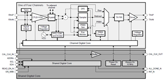
We are trying to understand the definitions of the registers and functional block better in DS125DF410. The datasheet uses both of the terms VCO and CDR and they look like two independent functions on the block diagram level:
As far as we know, CDR should be a standalone function with its own set of circuitry including an internal VCO. So the VCO block shown on the block diagram should not be part of the CDR function. Is our understanding correct? If so, can you let us know how the two relate to each other? For example, when we change the VCO divider value (bit 6:4 of register 0x18) manually, will the CDR function for the input signals be affected?

Thanks.

  • Hi,

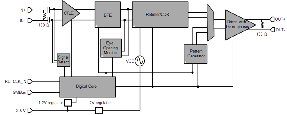
    I see how this block diagram might be confusing. I'm including below the block diagram for another TI retimer, the DS250DF410, which uses the same architecture.

    • There are two key functions implemented by the retimer, the clock and data recovery (CDR) and the sampling
    • The retimer recovers the clock from the input data using PLL functionality to lock the VCO to a specific frequency
    • Subsequently this recovered clock from CDR is used to clock the digital sampling logic to effective retime the input data, outputting a lower jitter version of it

    As far as we know, CDR should be a standalone function with its own set of circuitry including an internal VCO.So the VCO block shown on the block diagram should not be part of the CDR function. Is our understanding correct? If so, can you let us know how the two relate to each other?

     For example, when we change the VCO divider value (bit 6:4 of register 0x18) manually, will the CDR function for the input signals be affected?

    • The user does not need to manually configure the VCO
    • The user simply specifies the data rate that the CDR will attempt to lock to along with the CDR divider ratio. By default the retimer assumes divide by 1 ratio. The user has the option to force divide by 2 or divide by 4 ratio

    Thanks,

    Rodrigo Natal

  • Thanks, the block diagram you showed us looks more accurate.