This thread has been locked.

If you have a related question, please click the "Ask a related question" button in the top right corner. The newly created question will be automatically linked to this question.

TCAN1043A-Q1: SPLIT biasing

Part Number: TCAN1043A-Q1
Other Parts Discussed in Thread: SN65HVD251

Hi team,

My customer has a project which needs SPLIT pin mandatory. I know modan TCAN devices do not require SPLIT pin but, this is requirement from car OEM.

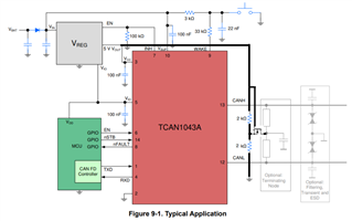
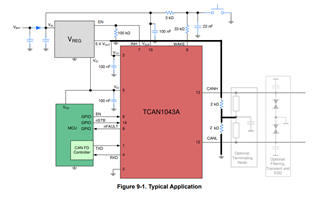
External 2kohm resistor divider like below image can imitate the SPLIT pin function? Is there any concern? Please give me your advice.

Regards,

  • Hi Hirai-san,

    We do not make any new devices with split pins anymore because our new devices are very good at keeping a consistent recessive bias. What you are showing in the picture is are split termination resistors which when paired with a split cap create a low pass filter that can help reduce noise on your bus.

    This is not the split pin function where it is actively outputting 2.5V in order to keep the recessive bias at 2.5V. If they really want the split pin they will have to go with a very old device like the SN65HVD251. This device has a Split pin called VREF that outputs a voltage that is half of VCC. I assume this is what they are looking for correct?

    I would see if you can move the customer away from the split pin requirement because they are getting a device with worse performance that can't handle as fast speeds or as large loading conditions. We do not have a device that has a split pin and all the features of the TCAN1043A. The industry has moved away from the split pin as a whole and it is no longer a requirement of CAN devices.

    Best,

    Chris

  • Chris-san,

    Please see the image again.

    I added 2kohm+2kohm resistor divider from 5V Vcc to make the 2.5V bias like SPLIT pin.

    My question is if the external circuit can imitate SPLIT pin function without any concern and negative effect.

    Regards,

  • Chris-san,

    To avoid a leakage from CAN bus when the node is in shutdown, I think a switch is required as below.

    Below external circuit can imitate SPLIT pin function?

    Regards,

  • Hirai-san,

    Are these 2K resistors connected to the CAN pins or will they just connect to the split termination resistors? If they don't connect to the CAN pins and you use split termination to connect the 2.5V to the split termination resistors then this could work. I would increase the resistance to lower the overall current of the 2.5V bias. What will happen is when you are driving dominant your CANH and CANL pins will have to fight this 2.5V bias that you are creating. That is why I recommend making it weaker. The device also supplies it's own internal bias of 2.5V. 

    I can check this in the lab for you but I don't have time right now, I can look at it next week if you remind me then. If you end up verifying this circuit works let me know.

    Best,

    Chris

  • Chris-san,

    Yes, it’s connected to the middle point of the split termination.

    I selected 2kohm because the equivalent circuit diagram of SN65HVDA1040 has 2kohm.

    Does the SPLIT function of HVDA1040 or HVD251 activated only during recessive state?

    If so, it’s may better that drive the FET switch by TXD signal instead of 5V Vcc.

    Please test this idea and make a suggestion next week.

    Best Regards,

  • Hirai-san,

    The SPLIT function is enabled in dominant and recessive state.

    I can simulate this in TINA and let you know the results by next week.

    Regards,

    Eric Hackett 

  • Eric-san,

    Thank you for your support.

    Do you have any update?

    Best Regards,

  • Hi Atsushi,

    I believe Eric is still working on this I will check with him tomorrow.

    Best,

    Chris

  • Hirai-san,

    I simulated this up to 5Mbps and saw no issues on the CANH, CANL, or RXD waveforms. This will be okay to use as SPLIT pin biasing in the customer setup.

    Regards,

    Eric Hackett