This thread has been locked.

If you have a related question, please click the "Ask a related question" button in the top right corner. The newly created question will be automatically linked to this question.

DS90UB953-Q1: Question about 954 and 953

Part Number: DS90UB953-Q1

Dear Team,

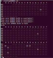
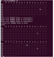
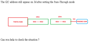
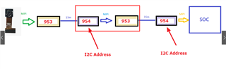
Customer use two pairs 983 984 to connect camera and SoC with 30M wired.

They faced some problems in I2C communication. Is there any way to avoid it?

Many Thanks,

Jimmy

  • Hi Jimmy,

    So they are using 2x 953 and 2x 954, correct?

    Which type of issues are they facing?

    Have they debug anything so far?

  • Hi Jaradat,

    Thanks for your great support!

    yes!954-953-954-953!please refer below.

    How would we connect the second 954 for same i2c address?
    Is it bypass mode at first stage 954-953?

    Many Thanks,

    Jimmy

  • If you are asking because you want to communicate with the Image Sensor through all these devices, then you can use the pass-throu mode by assuming the first 953+954 is link A and the second 953+954 is link B, and the image sensor as Adress 0xXY:
     
    SoC --> 954 (A) --> 953 (A) --> 954 (B) --> 953 (B) -->Image Sensor
     
     
    Program 954 (A):
    0x58[6]=1 for Pass-throu enabled
    0x5D: SlaveID[0] = 0xXY
    0x65: SlaveAlias[0] = 0xXY
     
    Program 954 (B):
    0x58[6]=1 for Pass-throu enabled
    0x5D: SlaveID[0] = 0xXY
    0x65: SlaveAlias[0] = 0xXY

  • Hi Jaradat,

    Thanks for your great support always! :)

    Current test result 

    - 1 serdes (0x3d) with our camera sensor. OK

    - 2 serdes (both with the same address 0x3D) + mipi sensor. FAILED


    ==============

    detail info

    -  1 serdes (0x3d) with our camera sensor. OK

    echo "1" >/proc/sys/kernel/printk
    modprobe i2c-dev          
    i2cdetect 0 -ya 0x03 0x74  
    echo "Make sure SERDES 0x3D is available!!"
    echo "Make sure SERDES 0x3D is available!!"
    echo "Make sure SERDES 0x3D is available!!"

    echo "config 1st SERDES 0x3d to 0x3C"
    i2cset -f -y 0 0x3d 0x00 0x79 b
    i2cget -f -y 0 0x3c 0x00
    i2cdetect 0 -ya 0x03 0x74  
    # RX_PORT0 read; RX0/1 write
    i2cset -f -y 0 0x3c 0x4c 0x01 b
    # CSI_PLL_CTL (Address 0x1F) 00 : 1.6 Gbps serial rate
    #i2cset -f -y 0 0x3c 0x1f 0x00 b
    # CSI_PLL_CTL (Address 0x1F) 00 : 800M bps serial rate
    i2cset -f -y 0 0x3c 0x1f 0x02 b
    # CSI_CTL (Address 0x33)
    i2cset -f -y 0 0x3c 0x33 0x03 b
    # FWD_CTL1 (Address 0x20)
    i2cset -f -y 0 0x3c 0x20 0x20 b
    # SlaveID[0] (Address 0x5D)
    i2cset -f -y 0 0x3c 0x5d 0x20 b
    # enable pass through
    i2cset -f -y 0 0x3c 0x58 0xde b

    - 2 serdes (both with the same address 0x3D) + mipi sensor not ok

    Many Thanks,

    Jimmy

  • Hi Jimmy,

    Can you please clarify the followings:

    - What is the I2C address for both SER?

    - What is the I2C address for both DES?

    - What is the I2C address for the Image Sensor?

    What do you write in the following registers for each DES:

    0x58, 0x5B to 0x6D

  • Hi Jaradat,

    1-2==>default ==>0x3d (both ) beacause it's cascaded PR production cable *2 and we can't set the I2C address via I2C seperately
    3==> 0x10
    4==> I had tried it. it is useless as figure.

    When the customer string together two groups of 953 954, and give an instruction to change the address, it will be changed to two groups at one time, and there is no way to change it separately.
    Is there any way to separate the commands for these two groups?

    It can't sensor the 2nd 954 I2c address(default 0x3d) on the cascade SerDes structure even HUB sets the different 0x3C on 1st 954.  

    Could you apply the command for real cascade SerDes experience?

    Customer use the pass-throu mode by assuming the first 953+954 is link A and the second 953+954 is link B, but still fail.

    Many Thanks,

    Jimmy

  • Dear Customer,

    Please be noted that the E2E support forums will undergo maintenance from Sept. 28 to Oct. 2, hence it will not be available during this time. If you need design support during this time, please contact your TI representative

    Normal E2E support should be back by Monday, Oct. 3.

  • Hi Hi Jaradat,

    Thanks for your great support!

    1-2==>default ==>0x3d (both ) beacause it's cascaded PR production cable *2 and we can't set the I2C address via I2C seperately
    3==> 0x10
    4==> I had tried it. it is useless as figure.

    When the customer string together two groups of 953 954, and give an instruction to change the address, it will be changed to two groups at one time, and there is no way to change it separately.
    Is there any way to separate the commands for these two groups?

    It can't sensor the 2nd 954 I2c address(default 0x3d) on the cascade SerDes structure even HUB sets the different 0x3C on 1st 954.  

    Could you apply the command for real cascade SerDes experience?

    Customer use the pass-throu mode by assuming the first 953+954 is link A and the second 953+954 is link B, but still fail.

    Many Thanks,

    Jimmy

  • Hello Jimmy,

    can you please tell me what are you trying to achieve? Are you just trying to configure only the image sensor?