Hello,
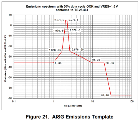
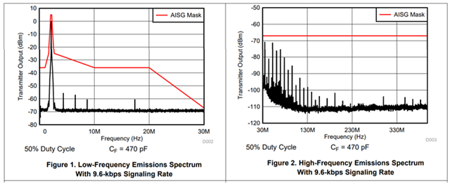
For SN65HVD6x, please let me know the measurement setup for ASIG emission spectrum (fig 21, fig 1, and fig 2 in SN65HVD63 datasheet). My customer intends to measure the spectrum under the same setting in their lab. Thank you!


This thread has been locked.
If you have a related question, please click the "Ask a related question" button in the top right corner. The newly created question will be automatically linked to this question.
Hello,
For SN65HVD6x, please let me know the measurement setup for ASIG emission spectrum (fig 21, fig 1, and fig 2 in SN65HVD63 datasheet). My customer intends to measure the spectrum under the same setting in their lab. Thank you!


Hi Ella,
These test setups are defined by the TS 25.461 standard - which you can find here: https://www.etsi.org/deliver/etsi_ts/125400_125499/125461/13.01.00_60/ts_125461v130100p.pdf
Best,
Parker Dodson
Hi Parker,
Thank you for response! I check the document but my customer is asking about the physical setup; equipment being used between OOK output and IC input, measurement point, etc., so that they can proceed the ASIG emission spectrum measurement under the identical setup in their lab.
Hi Ella,
Figure 21 is a mask - not a measurement.
The emissions setup is:
1. RXIn to Ground has a 470pF capacitor as mentioned in datasheet - note (2)
2. The output is coupled to coax cable with 50 Ohm characteristic impedance then fed into a spectrum analyzer. As denoted in datasheet tables - there isn't anything else that is really specified for setup. Minimize the connection distance between analyzer and output to improve results as the longer the cables the worse it will perform.
That's the hardware setup - the mask is what is being tested against (essentially a limit line). Attach output to coax and have RXin cap to ground of 470pF.
Best,
Parker Dodson