This thread has been locked.

If you have a related question, please click the "Ask a related question" button in the top right corner. The newly created question will be automatically linked to this question.

SN65ALS176: RS485 Bus Communication : Termination Resistor Topology

Part Number: SN65ALS176
Other Parts Discussed in Thread: THVD8000

Dear Sir/Madam,


We require technical support for the RS485 termination resistor requirement. We have used SN65ALS176 as RS485 Transceriver.

Below is our circuit diagram.

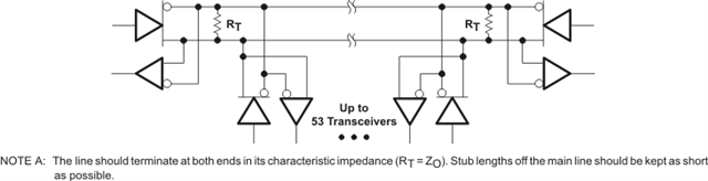
All FMs (Functional Modules) card having termination resistors and there are total 25 x FMs in network.
We have observed that after increasing number of FMs above 10, we are facing communication stability issue, so let us know how we need to put termination resistor FM cards?

Is our Termination resistor topology creating this stability issue ? What will be the appropriate Termination Resistor Placement method as per RS-485 Guidelines in such type of networks?

Kindly guide us. Your earliest response will help us lot.

We are planning to work over this weekend so your reply in terms of circuit correction (if any), we want to implement your suggested changes and want to test it overnight.

  • There should be exactly two terminations, at both ends of the bus. And they should be at the actual ends of the cable, even if there is no transceiver at that point. Change your modules to allow enabling the termination with a jumper. Alternatively, remove the termination from all modules, and put special termination modules at the ends.

    Failsafe resistors are needed only once, and can be placed anywhere on the bus.

    See The RS-485 Design Guide and Ten Ways to Bulletproof RS-485 Interfaces.

  • Hi Himanshu,

    So this is not within spec for RS-485 systems and the reason you are seeing stability issues is at least partially due to the system setup. 

    1. System Topology should either be daisy chained or use junction boxes.

    2. In the RS-485 systems only the first and last nodes on the bus are terminated and this resistor value should be 120 Ohms. 

    3. The pull up resistor on A  - to bias the 'A' line only 1 node needs the external pull-up - it is not required on every node. This is the same for the pull-down on "B".

    4. The impedance on the "A" line to ground needs to be >= 375 Ohms. This can be found by taking the effective parallel impedance of the pull-up resistors and the input impedance of the RS-485 transceivers (where input impedance is #nodes supported * 375 - so for this device 12K). The same analysis and conclusion can be drawn on the "B" line as well.

    Essentially RS-485 bus should more or less look like this:

    The above picture doesn't include bias resistors - but those are acceptable.

    I do have a few questions to ensure the correct values are being used:

    1. What is the intention of the pull-up on "A" and pull-down on 'B" - i.e what are these resistors trying to accomplish? Is it fail-safe biasing?

    2. What bus topology is being used in the system?

    3. Can you confirm the component values: RT = 142 Ohms; R_PU = R_PD = 392 Ohms - is this correct? 

    4. What is the bus length of the application? 

    Please let me know on the above four questions so I can also check the design if there could be any other potential issues.

    Best,

    Parker Dodson

  • Dear Parker Dodson,

    Thank you very much for your detail answers and prompt technical support. 

    Please find our feedback in same sequence as per your review points.

    1. Looks like our RS-485 bus has "Junction Box" System Topology. Kindly check image of our RS-485 System Bus. Please confirm.
    2. We are agree with your point and will implement resistor values as per your suggestion. 
    3. With respect to attached image of our System Bus "Junction Box" Topology, total cable length will be exceeded >100 meter. Kindly suggest us do we need single fail-safe terminology or dual fail-safe terminology for Pull-up and Pull-down resistors on Line-A and Line-B Respectively.
    4. Your explanation is quite interesting. But I am unable to identify how 12K value has been derived (i.e. #nodes supported * 375 - so for this device 12K) as well as didn't get the value of effective parallel impedance of pull up resistors and input impedance of RS-485 transceiver. Kindly guide us as we are little bit new in this field. 

    Our reply about your additional questions regarding Pull-up and Pull-down resistors terminology

    1. Yes we need fail-safe biasing.
    2. Junction Box Bus Topology we have used
    3. Request you to guide us about formulae to calculate proper values of Rt, Rpu and Rpb with respect to our Junction Box topology.
    4. Kindly see attached image to get the total length of Bus. We are seeing that our bus length will be > 100meter.

    Thanks in advance for your great support to fix out this issue. 

  • RS-485 transmitters are designed for a load of about 60 Ω (two 120 Ω resistors in parallel). Your topology has 25 resistors in parallel, which creates a load of less than 5 Ω.

    To get the load down to 60 Ω, replace all 120 Ω termination resistors with 1500 Ω ones. This means that the cables are no longer properly terminated, and that there will be signal reflections at the nodes, so you will have to greatly reduce the frequency of your signals.

    The fail-safe resistors must be able to create a voltage drop of more than 0.2 V over the termination resistors. With a 5 V supply, 680 Ω for both should be fine.

  • Hi Himanshu,

    1. I think I wasn't clear enough - when I said junction boxes - I meant junction box + backbone - please see below (bottom left):

    I am not 100% on your topology - I think it may be closer to a start network - which isn't ideal for RS-485 buses.

    2. Ok - so this termination style is suggested - but it only works well due in the bottom two topologies. I think you may have a star network which would require terminations on every node - and the 120 Ohm is too low for 25 nodes + when adjusting to a higher termination you get a lot of reflections. Even if the data rate is lowered - the transition speed is fixed and the harmonic content from the transition (which is fast since this part is at 35Mbps max data rate) will reflect. We have tested a system that can work in a Star network - but the caveat is that it includes line drivers and we tested it with a special RS-485 device (THVD8000) which uses OOK modulation on the bus signal - I have added a note here: https://www.ti.com/lit/an/slla573/slla573.pdf?ts=1664204264810&ref_url=https%253A%252F%252Fwww.google.com%252F but we don't have data that would support using this with other parts - but it may be possible. Using the line driver allows 120 Ohm terminations on multiple nodes without overstressing the driver on the RS-485 transceiver itself. 

    3. Fail safe resistors are only needed at one node as long as all the nodes are connected. There is a slight issue however - fail safe resistor values should be at 680 Ohms to set an idle voltage of about 200mV (680 from VCC to A and 680 from B to GND assuming an eq. termination resistance of 60 Ohms) however this violates the impedance from A or B to ground  (minimum 375 Ohms)- as the condition for minimum fail-safe value is: R_FS >= (375 * R_in) / R_in - 375). Which for this setup R_In = 12K/25 = 1.714K ohms which won't set a proper idle voltage. That being said - if 680 is used  there may be a bit more attenuation on the differential signal than spec'd as its out of range however I don't think the impedance is low enough to cause damage if the 680 is used. 

    4. The RS--485 standard dictates a input leakage vs bus voltage spec called the unit load

    One of the corners is 12V and 1mA  which gives 12K of input impedance.  The 12K load line is a standard approximation used to simplify the input impedance of the device. This is a standard RS-485 device that is rated for 1 Unit load which is 32 nodes on a bus. The 32 nodes when taking the 12K ohm in parallel is equal to 375 Ohms (12K / 32 = 375). The 375 Ohm also is what is used as common mode loading to simulate a fully loaded bus when testing the device under the common mode ratings. So on devices with 1/2, 1/4, or 1/8 unit loads we can approximate the input impedance as 24K, 48K, and 96K respectively. It isn't always necessarily going to be the appx. impedance but it is a good estimate of how RS-485 devices behave. This device specifically supports 32 nodes so the eq. input impedance can be approximated as 12K. 

    The reason you take them in parallels is that an RS-485 bus with 25 nodes has the "A" pins in parallel with all of the A pins and the same can be said for the B pins with all the "B" pins. The nomenclature is a bit weird because there are a lot of shortcuts/assumptions built in. I have added a design guide that really covers the basics of RS-485 design that is super helpful: https://www.ti.com/lit/an/slla272d/slla272d.pdf?ts=1664206175196&ref_url=https%253A%252F%252Fwww.google.com%252F - also if you can access the RS-485 standard it isn't very long of a read and it may have some more information - but the design guide I attached above is going to be very helpful in most applications. 

    1. For proper fail-safe biasing there is going to be some attenuation on the main line signal as I state a little higher up in this reply. So there could be some issues around max conditions / longer bus length (unless a line driver is added than this point isn't important). It will cause the app to be out of spec but I don't suspect damage would occur I just suspect some derating of the driver specs. 

    2. Can you confirm with my first picture in this reply - just to clarify as I didn't specify the type of junction box topology and I apologize for that. 

    3. Rt should equal Characteristic impedance of transmission line and there should be 2 terminations - unless its in a star topology than they all need terminated and you can possibly use a line driver to overcome the low impedance. We have had this work for one of our parts that uses OOK modulation - while I think it may be possible to use this part with a line driver to overcome the low impedance - encoding schemes like Manchester encoding (using the THVD8000 overrides the need for special encoding that's why we used that part in the app note)  would have to be employed to remove DC/ near DC frequencies from the data stream. RS-485 spec wants 60 (+/- 10%) Ohms of resistance between A and B - in normal systems this is 2 120 Ohm resistors - depending on topology that may change - using a line driver would overrule the minimum resistance requirements and decrease the minimum resistance quite a bit..

    4. Bus Length of >100 meters should be that big of an issue - but there will be some impact to max data-rate as the larger than bus the slower the data rate needs to be. RS-485 devices at lower speeds can peak at around 1.2km. 

    If you could please confirm that the topology is the junction box with backbone or if it resembles closer to star network as described in the first picture that will determine the next steps. Also if you know the data-rate could you please share ? 

    Best,

    Parker Dodson

  • Dear 

    Thank you very much for your great support. 

    Can you please share your email ID so we can communicate further?

    Also e2e forum will go under maintenance, it will be good if we can do technical conversation without any interruption. 

  • Dear Parker Dodson,

    Thank you very much for your great support. Let me check your given documentation. 

    Can you please share your email ID so we can do communicate further?

    Also e2e forum will go under maintenance, it will be good if we can do technical conversation without any interruption. 

  • HI Himanshu,

    I will send a message (it might be in the form of a friend request - as I am not sure if I can direct message without doing that first on E2E)  to you with my email and we can continue through the E2E disruption off forum.

    I will be closing this thread since we are going off forum - but feel free to reopen if  you'd like to continue discussion here.

    Best,

    Parker Dodson