This thread has been locked.

If you have a related question, please click the "Ask a related question" button in the top right corner. The newly created question will be automatically linked to this question.

TFP401A: ODCK is set to free run, but there are individuals that ODCK does not work.

Part Number: TFP401A
Other Parts Discussed in Thread: TFP401,

Hi Experts,

Good day.

The TI product of interest is the TFP401APZP.
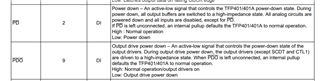
The specification states that if the mode settings are DFO: Lo, PIXS: Lo, OCK_INV: Lo, ODCK will be free-running.
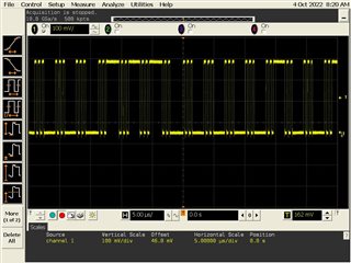
I made the same settings, but even if I supplied power to the TFP401APZP, I could not confirm the movement of the waveform from ODCK.
Even if the clock is not input to the RxC signal on pins 93 and 94, an indeterminate waveform should be output from ODCK, but it is not output.

Is this a product defect? please advise.

Keep safe.


Regards,

Josel

  • Josel

    What are the state of /PD and /PDO? Are they high or low?

    Thanks

    David

  • Hi David,

    Good day.

    Nothing is connected to PD and PDO. Set Hi with internal pull-up. As for other settings, ST is Hi and STAG is Hi.

    Please advise and keep safe.


    Regards,

    Josel

  • Josel

    Just to take a step back, if you supply the right clock frequency on RXC+/-, are you able to see the correct clock output on the ODCK?

    Thanks

    David

  • Hi David,

    Good day.

    If I supply the right clock frequency on RXC+/-, I can see the correct clock output on ODCK.
    This issue is incorporated into our product, and we recognize it as a defect, so we hope to resolve it as soon as possible.

    Please advise.

    Keep safe.


    Regards,

    Josel

  • Josel

    I am able to duplicate the free running ODCK on my bench board. 

    Below is my bench EVM configuration pin setting,

    PDO: 3.3V

    PIXS: 0V

    PD: 3.3V

    OCK_INV: 3.3V

    DFO: 0V

    ST: 3.3V

    STAG: 3.3V

    If I pull PDO low, then the ODCK will stop as well.

    Are you seeing this issue on multiple units?

    Thanks

    David 

  • Hi David,

    Good day.

    The configuration pin setting for my circuit board is the same as the configuration pin setting for your circuit board.

    PDO: 3.3V
    PIXS: 0V
    PD: 3.3V
    OCK_INV: 3.3V
    DFO: 0V
    ST: 3.3V
    STAG: 3.3V

    PDO is not set to Lo, but ODCK has stopped working.

    I confirmed the operation of ODCK with 6 parts, and 2 parts of them have the same phenomenon.

    Please advise.

    Keep safe.

    Regards,

    Josel
  • Josel

    Can you please work with our local office to submit these 2 parts for FA? 

    I am also curious on why you want the ODCK to be free running since the ODCK behavior is not guaranteed when it is free running. 

    Thanks

    David 

  • Hi David,

    Good day.

    In a normal product, ODCK outputs a synchronized signal at the timing when RxC+/- is input.
    Also, ODCK becomes free-running when the RxC+/- input disappears.
    The top waveform is ODCK and the bottom waveform is RxC+/-.
    In the defective product, ODCK outputs a synchronized signal at the timing when RxC+/- is input.
    ODCK is fixed at Hi or Lo at the timing when the RxC+/- input disappears.

    Please advise.

    Keep safe.


    Regard,

    Josel

  • Josel

    Can you work with our field office and have these units submitted for FA?

    Thanks

    David

  • Hi David,

    Good day.

    The customer responds.

    If I ship a defective product, there will be nothing to check. So I would like to send it as a last resort.
    I will explain how I came to check the operation of ODCK this time.
    When the PC's HDMI signal is input to the corresponding IC and the PC is put into sleep mode, SCDT changes to Lo after a considerable amount of time has passed since DE has stopped transitioning.
    Our system checks both DE and SCDT to determine the presence or absence of a signal.
    This SCDT delay causes our system to malfunction.
    As for content related to SCDT, I think that it is caused by the delay of SCDT because ODCK stops without free-running.
    ODCK free-running does not cause SCDT lag operation.

    CH1:HSYNC
    CH2:VSYNC
    CH3:DE
    CH4:SCDT

    Please advise.

    Keep safe.


    Regards,

    Josel

  • Josel

    The TFP401A monitors activity on DE to determine if the link is active. When 2^18 clocks produced by an on-chip free running oscillator whose frequency is around 10-15 MHz pass without a transition on DE, the TFP401 considers the link inactive and SCDT is driven low. So the transition time between DE transition to SCDT low is ~17-26ms.

    Thanks

    David

  • Hi David,

    Good day.

    The customer responds.

    Defective products have a DE transition to SCDT low transition time of more than 1 second.
    If the DE to SCDT low transition time is typically 17-26 ms, would you consider anything longer than 1 second to be defective?

    Please advise.


    Regards,
    Josel

  • Josel

    We would need to take a look at these units before determining if they are truly defective or not.

    Thanks

    David

  • Hi David,

    Good day.

    Is there any way for us to check the operation of the on-chip free-running oscillator?
    Is the behavior of this on-chip free-running oscillator identical to ODCK?
    Have you completed all possible verifications before sending the unit?
    Is there any way to solve the problem other than sending the unit?


    Regards,

    Josel

  • Josel

    The free-running oscillator is internal. But I would like to have at least one unit back and see if we can catch any failure with it.

    Thanks

    David