This thread has been locked.

If you have a related question, please click the "Ask a related question" button in the top right corner. The newly created question will be automatically linked to this question.

1394 bus initialization problems

Other Parts Discussed in Thread: TSB82AA2

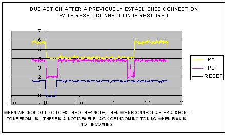
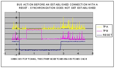
We have a new design with a TSB81BA3 (and TSB82AA2) connected to a Unibrain 1394 card in an XP PC with their analyzer software. Sometimes they synchronize at reset, many times they don't when we power-up our side (without making any changes). When they synchronize, the connection seems pretty robust (does not drop out). Can anyone suggest an analyzer/scope setup that will allow me to capture the B-mode tone waveform for analysis?

  • Hello Robert,

    Do you have an issue with the TSB81BA3 ? 

    Do you have waveforms or bus analysis traces of what are you observing?

    See below:

    "Attached is an example of what they can capture.  They should connect a scope to the TPA and TPB signals.

     In this capture, initially two 1394b devices are powered up and connected at S800 speed.  Then power is removed from one device, the other device is toning (Waiting for a device to connect).  When power is applied to the other device (Or when the cable is plugged), TPBIAS is detected(It is then determined if a 1394a or 1394b device is present), then the S800 speed negotiation occurs and the S800 connection is present."


    Regards.

  • Thanks Elias,

    What TEK model produces this display? I only have a 150MHz scope without storage but need to produce a waveform on our system like the waveform you have provided. I cannot tell where my synchronization problem is right now, therefore need to look on the media for clues. We are able to read/write the TSB82AA2 and access the TSB81BA3 through the LLC OHCI interface reliably but cannot figure out why synchronization is such a problem. I'd look for poor signal conditioning, etc if I had the capability.

    We have had some success synching up but it always ends up in legacy mode rather than beta mode despite both ports being capable of beta mode operation (both are bilingual).

    Thanks,

    Robert Lindner

  • Hello Robert,

    Verify your configuration of pins BMODE, DS0, DS1, DS2, they must be tied low for 1394b operation.

    The TPBIAS and TPA+/- are needed even if your communication is going to be only in 1394b mode.

    Attached is a reference schematic, take only page 2 and discard the other pages.

    Regards.4857.9873274.pdf

  • Thanks Elias,

    The 4 signals you mention are as you suggested.

    I am comparing the waveforms you provided with those that I am getting (on my 150MHz scope) and have a few discrepancies/questions.

    First, the TPBIAS we are receiving when we are powered down does not persist indefinitely. Is this normal?  How long should we expect it to persist? I get about 1 second worth after removing power/toning. I try to power up while the TPBIAS is asserted, but establishing synchronization does not improve.

    Second, after power is reapplied, we tone within 100msec and it shows yours to have about 600msec delay. Will this make a difference? Will the same delay time be needed to occur with a RESETZ? We have RESETZ and the LLC's G_RST_N tied together. Is this inappropriate?

    Last, again after power is applied, the speed negotiation looks to take approximately 600msec (as yours does) and then we see an attempt to connect but it only lasts less than about the duration as a 40msec toning interval and then both sides return to speed negotiation toning. The PHY properly reports in Page0 (for Port 0) that synchronization has not been established. Can you tell me the criteria for synchronization? I cannot find anything specific in the documentation, including the 1394b standard.

    Thanks again,

    Robert Lindner


  • Elias,

    Forget the previous line of questioning. I now have a specific condition (that actually establishes communication) that I need an explanation for.

    As I stated in the first post, we can and do establish communication and synchronization at times, seemingly at random. Only now I can explain how we can get there and stay there through power cycles as well.

    I have noticed that only when we are actually communicating and I power down or reset our node, the TPBIAS nodes on our side on both TPA and TPB are 0 volts (as well as no toning being received on TPB). I can resume power and our node comes back online and cause a bus reset and be detected on the other end. I can do this indefinitely (meaning cycle power and resume communication).

    Only when I unplug the cable will I lose the "connection" where I cannot re-sync. Cycling power and resetting our node will not re-establish a connection. At this time, we are receiving incoming tone or bias (depending on the point in time after we power down). This is when we cannot re-establish communication no matter how many attempts are made.

    Restating, when we power up or come out of reset while we are receiving beta toning or bias, we will not re-sync.

    So in order to get through this obstacle, I will short the 5.1K Ohm bias sense resistor on our TPB side and power cycle until we again receive neither tone nor bias from the other node. I can remove the short and will successfully reconnect.

    So the questions are: What causes the other node to stop toning and biasing AND why do we need this condition to make a successful connection.

    Thanks for your help,

    Robert Lindner


  • Hello Robert,

    I've been thinking about this, if the nodes are able to sync the first time, unplugging the cable should cause a bus reset  and so plugging it again, so there should not be any problem. Can you send some bus analyzer traces when the error occurs? Are you powering up the system with the 1394 cable connected?


    Please confirm if I understood your statement correct:

    1)  You can sync both nodes (TSB82AA2&TSB81BA3 with your Unibrain card), then you may power cycle your system and the nodes will sync again with no problems, also you can send bus reset via software and there is no re-sync problem. Am I right?

    2) The nodes are sync'd and then you unplug the cable, when you plug again the cable you cannot get the nodes sync'd again. Am I right?

    3) Once the unplug and plug event happens, you cannot get the nodes sync'd even if you make a power cycle and/or send a bus reset. Am I right?

    Can you explain again the following "Restating, when we power up or come out of reset while we are receiving beta toning or bias, we will not re-sync."

    Regards.

  • Elias,

    Correct on all 3 points.

    Explanation: While observing both TPA and TPB signals, sync will only be established when the remote node is neither toning nor biasing when we come back online. Contra-positively, if the remote node is either sending a bias (lasting 1.5 seconds after we go off-line) or a tone (beta mode steady-state condition), we will not sync up when we come online. Only through the manipulation of the received bias node (on TPB) I described previously, can I induce the remote node to stop sending both tone and bias for us to be able to sync.

    Hope that clarifies it.

    Thanks,

    Robert

  • Hello Robert,

    A schematic and bus analyzer traces as well as your scope captures will help a lot on debugging this.

    Can you send them?

    When the connection is successful, are you having a 1394a or 1394b connection?

    While the device is toning(Looking for a 1394b connection), TPBIAS goes away, after the device tones and does not see a 1394b node attached it applies TPBIAS looking for a 1394a connection, if no 1394a connection is present, it returns to start toning looking for a 1394b connection again (And this is repeated until a connection occurs). 

    Regards.


  • Here are two scope captures for now (keep in mind it is only a 150MHz scope):

    WHEN WE DROP OUT SO DOES THE OTHER NODE, WE CAN RECONNECT AFTER

    A SHORT TONE FROM US - THERE IS A NOTICEABLE LACK OF INCOMING TONING

    WHEN BIAS IS NOT INCOMING.

    WHEN WE STOP TONING, THE OTHER NODE TONES/BIASES/TONES ONCE.

    I'm working on schematics and bus analyzer traces.

  • Our circuit schematic is attached. A circuit change was made to eliminate the DC blocking caps C130-133, thinking beta-only mode can be used. Also, the oscillator was changed to a 1.8V part as required.

    Pgs7-8.pdf
  • Hello Robert,

    Some comment about the schematic:

    1) TPA0+/- must be connected to TPBIAS0 through a 56.2 ohm resistors, and TPBIAS0 should have two parallel capacitors to ground (270pF and 1uF).

    2) I would remove C130, C131, C132 and C133, they could block the DC component (TPBIAS).

    Try that out please.

    Regards.

  • I have actually made both changes since the schematic was drawn (sorry for not sending a corrected schematic). The DC blocking caps are shorted and TPBIAS0 is connected to the R75-76 junction (with the parallel caps to ground).

    Please let me know if anything else in the circuitry looks awry.

    Are there any register settings in the PHY that need to be set a certain way or will synchronization occur without software intervention?

    Thanks again.

    Robert Lindner

  • The synchronization will occur without software intervention.

    Can you do the following:

    1) Measure or capture the state of pins CNA and CPS when:

           a) Devices are synchronized.

           b) The cable is unplugged.  

           c) The cable is plugged back but devices can't synchronize.

    2) Do the same of point 1) after connecting CPS to cable bus power through a 400K resistor.


    Regards.


  • For 1 (no cable power sense):

    When synchronized: CNA = LO, CPS = LO

    When cable unplugged: CNA = HI, CPS = LO

    When connected, not synchronized: CNA = HI, CPS = LO

    For 2 (cable power [12V] through 390K resistor):

    When synchronized: CNA = LO, CPS = 3.6V

    When cable unplugged: CNA = HI, CPS = LO

    When connected, not synchronized: CNA = HI, CPS = 3.6V

    I hope this helps. Thanks again,

    R Lindner

  • Added changes to schematic (attached).

    Pgs7-8 with edits.pdf
  • Hello Robert,

    Please connect TPB1+/- and TPB2+/- to ground.

    Regards.

  • Elias,

    I implemented your suggestion but it has not resulted in any change in our situation. We still need to hold TPB bias voltage sense node to ground while cycling power (more than once, typically) to restore sync/communication. We are considering replacing the PHY device itself in case something has affected it.

    Robert L